HVAC / Air Conditioners
Spare Parts List for EIP 10970GB-GB Spot Cooler
A comprehensive spare parts list and internal component identification guide for the EIP 10970GB-GB Spot Cooler. Includes a detailed breakdown of parts and an annotated diagram for maintenance and repair.
Table of contents
Important Information for EIP 10970GB-GB
This document serves as the official spare parts list and component identification guide for the EIP 10970GB-GB Spot Cooler (BKool12). It is intended for use by technicians and owners to identify internal components for maintenance, troubleshooting, and repair purposes. The unit operates on a 230V / 50Hz power supply.
Spare Parts List
The following components are identified for the EIP 10970GB-GB model:
- Electrical Components: Delay Timer (1), MY4 Relay (10), Temperature Controller (12), Microswitch (13), Thermistor (14), Rocker Switch (15), Fan Motor (16), Contactor (27), Indicator Lamps (28, 29, 30), Male/Female Plugs and Crimps (31-34).
- Cooling System: Evaporator Coil (4), Condenser Coil (5), Capillary Tube (6), Filter Dryer (7), Pressure Switches (8, 9), Frostat (11), Compressor (35).
- Mechanical & Housing: Outlet Grille (3), Fan Inlet Ring (17), Fan Assembly (18), Inlet Ring (19), Castors (20, 21), Quick Release Catch (22), Extension Spring (23), Condensate Container and Cap (24, 25), Flexible Duct (26).
- Cabling: 3 Meter Mains Cable (2).
Component Identification
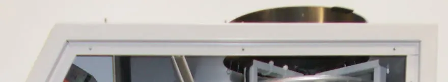
Refer to the internal diagram provided in the document to locate these parts. The diagram provides a visual reference for the placement of the compressor, fan assembly, electrical relays, and condensate management system. Ensure the unit is disconnected from the power supply before attempting any inspection or part replacement.
Practical help
Common problems
Unit not cooling
Inspect the Compressor (35), Fan Motor (16), or Pressure Switches (8, 9) for signs of failure or disconnection.
Water leakage
Check the Condensate Container (24) and Condensate Container Cap (25) for cracks or improper seating.
Electrical failure or unit not starting
Verify the status of the Delay Timer (1), MY4 Relay (10), and Contactor (27). Ensure the Mains Cable (2) is intact.
Before use
- Verify that the power supply matches the 230V / 50Hz specification.
- Ensure the Condensate Container is correctly positioned.
- Inspect the unit for any visible damage to the housing or internal components.
- Check that the Outlet Grille and Inlet Ring are free from obstructions.
Specs in practice
- 450PSI / 10PSI
- Pressure switch cut-out settings for the refrigeration system.
Images and diagrams
- The diagram on page 2 provides a top-down internal view of the unit.
- Numbered callouts correspond directly to the Spare Parts List on page 1.
- The diagram highlights the location of the compressor, fan assembly, and electrical control board.
Model compatibility
- Parts are specific to the 10970GB-GB model (BKool12).
- Ensure replacement parts match the voltage and specifications listed in the parts table.

Manual page author
Michael Turner
Technical manual editor
Reviews PDF manuals for structure, safety notes, and practical product details so readers can find the right information quickly.