Electronics / Monitors
Ernitec 0070-1322A Mercury Network Camera User Guide
Quick setup and installation guide for the Ernitec 0070-1322A Mercury Network Camera, covering mounting procedures, OSD menu navigation, and lens adjustments.
Table of contents
Quick guide from the manual
This document provides essential instructions for the installation and initial setup of the Ernitec 0070-1322A Mercury Network Camera. It covers physical mounting, cable connections, and OSD menu operation. Always ensure the device is installed in a stable environment, protected from moisture and extreme temperatures, and powered by a compliant LPS-standard power adapter.
Device Structure
The camera features a multi-function switch for OSD menu navigation. For models without PTZ, the switch allows you to enter menus (SET), navigate (UP/DOWN/LEFT/RIGHT), and switch video modes (AHD, TVI, CVBS, CVI) by holding specific buttons for 5 seconds. For PTZ models, the SET button cycles through Pan/Tilt, Zoom, and Camera modes.
Device Installation
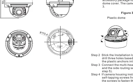
Installation requires using the provided template sticker to drill holes for plastic anchors. The camera can be mounted on ceilings or walls. For plastic dome models, the cover is removed by pressing and rotating counterclockwise. For vandal dome models, use the included T15 screwdriver to remove the cover screws. Ensure the dome cover is installed at least half an hour after the camera is powered on to prevent moisture buildup.
Lens Adjustment
After installation, adjust the lens angle horizontally and vertically. For AF lenses, use the Front-end Configuration; for MF lenses, use the focusing lever. Note that the focusing lever is locked by default; loosen it counterclockwise before adjustment and tighten it afterward.
Safety and Maintenance
- Use only the provided accessories.
- If installed outdoors, take measures to prevent insect and moisture ingress.
- Clean the device with a soft, dry cloth; use a neutral cleanser for stubborn dirt.
- Ground the device if installed in areas with unsteady voltage or frequent lightning.
- Disconnect all cables immediately if liquid enters the device.
Manufacturer information
Ernitec
Practical help
Common problems
Moisture inside the dome
Install the dome cover at least half an hour after the camera is installed and powered on.
Focusing lever is stuck
The lever is locked by default. Loosen it in a counterclockwise direction before attempting to adjust the focus.
Video mode needs changing
Use the multi-function switch to hold the corresponding button (UP/DOWN/LEFT/RIGHT) for 5 seconds to switch between AHD, TVI, CVBS, and CVI modes.
Before use
- Verify all items from the packing list are present (Camera, T15 screwdriver, M3 screwdriver, plug wrench, screws, anchors).
- Ensure the power supply meets the input voltage requirements (12V DC or 24V AC).
- Check that the power adapter is marked with the LPS standard.
- If installing outdoors, prepare insect- and moisture-proof measures.
- Remove the protective vinyl from the dome cover.
Specs in practice
- LPS Standard
- Limited Power Source; required for safe operation and to prevent damage.
- BNC Connector
- Standard interface for connecting the video signal cable.
Images and diagrams
- Figure 2-1: Shows the connection of the BNC video cable and power cable.
- Figure 2-2: Illustrates the multi-function switch used for OSD navigation.
- Figure 3-3: Demonstrates how to open the plastic and vandal dome covers.
- Figure 3-7: Shows the location of the focusing lever and main body fixation screws.
Model compatibility
- The camera supports multiple video modes: AHD, TVI, CVBS, and CVI.
- Large domes may require specific Phillips stainless screws (included) for mounting on junction boxes to maintain waterproof integrity.

Manual page author
Emily Carter
User documentation editor
Prepares concise manual descriptions and highlights the most useful setup, operation, and maintenance information for readers.