Electronics / Speakers Soundbars
Focal FDP SPORT V2 4-Channel Moto & All-Terrain Amplifier Manual
Comprehensive operation and configuration guide for the Focal FDP SPORT V2 4-channel amplifier, covering installation modes, wiring diagrams, and troubleshooting.
Table of contents
Manual images
Jump to the sectionProduct Overview
The Focal FDP SPORT V2 is a high-quality, compact Class D amplifier designed for motorcycles and all-terrain vehicles. It features a robust aluminum chassis for high thermal dissipation and a conformally coated circuit board for added water resistance. The amplifier is engineered to provide flexible audio configurations, including 4-channel stereo, 2-channel bridged, and 3-channel mixed modes.
Configuration Modes
The amplifier supports three primary configurations to suit various audio setups:
- 4-Channel Stereo Mode: Ideal for powering four separate speakers. Requires setting the mode switch to NORM.
- 2-Channel Bridged Stereo Mode: Provides higher power output for two speakers. Requires setting the mode switch to BRIDGED.
- 3-Channel Stereo & Bridged Mono Mode: Combines stereo speakers with a mono subwoofer channel.
Users must select the appropriate input mode (2IN or 4IN) based on the source signal. For specific Harley-Davidson installations, a 4-inch patch harness may be required when using certain input configurations.
Crossover and Gain Settings
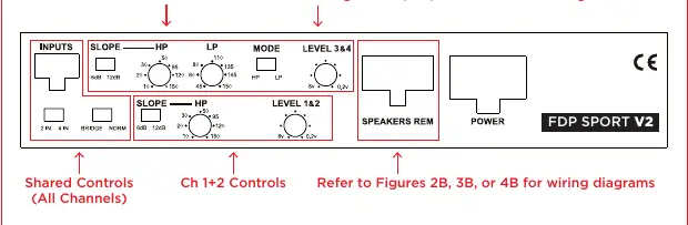
The FDP SPORT V2 features highly adjustable crossover controls, allowing for High Pass (HP), Low Pass (LP), and Band Pass (BP) filtering. Users can select between 6dB/octave and 12dB/octave slopes. Gain controls are provided for each channel pair to match the source output level. Proper adjustment of these controls is essential for optimal sound quality and to prevent damage to speakers.
Installation and Safety
Installation should be performed with attention to polarity and secure connections. The amplifier includes protection against DC, short circuits, thermal overload, and polarity reversal. It is recommended to ensure adequate ventilation, as the amplifier should not be covered or mounted flush into a hole. Always verify the 50A fuse at the battery and ensure all power and ground connections are tight.
Troubleshooting
If the Focal sign does not light, check the power and REM terminal voltages (12-15V), verify the REM wire connection, and inspect the internal fuses. If the sign is flashing, the amplifier may be overheating or experiencing an internal fault. In case of no sound, verify the source signal, check for shorted speaker wires, and ensure all crossover switches are correctly positioned for the intended setup.
Manufacturer information
Focal
Practical help
Common problems
Focal sign does not light
Check power/REM voltage (12-15V), verify REM connection, check battery fuse, and inspect internal fuses.
Amplifier blows fuse on startup
Check for reversed power and ground polarity at the amplifier and battery.
Focal sign is flashing
Check for overheating (ensure ventilation) or internal fault; check speaker wires for short circuits.
No sound
Verify source signal, check for shorted speaker wires, ensure correct switch positions, and verify crossover settings.
Before use
- Verify battery voltage is between 12V and 15V.
- Ensure all power and ground connections are tight and have correct polarity.
- Check that the 50A battery fuse is intact.
- Confirm the amplifier has adequate ventilation.
- Ensure speaker wires are not shorted.
- Verify all input and mode switches match the desired configuration.
Specs in practice
- 4 x 150W RMS @ 4 ohms
- Power output per channel in 4-channel mode.
- 2 x 400W RMS Bridged @ 4 ohms
- Combined power output for two channels in bridged mode.
- Frequency Response: 20-30KHz
- The range of audio frequencies the amplifier can reproduce.
- Signal/Noise Ratio: 95dB
- Indicates the clarity of the audio signal relative to background noise.
Images and diagrams
- Figure 1: Overview of control panel adjustments for channels 1-4.
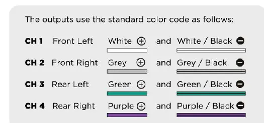
- Figure 2B: Wiring diagram for 4-channel stereo mode.
- Figure 3B: Wiring diagram for 2-channel bridged mode.
- Figure 4B: Wiring diagram for 3-channel stereo and bridged mono mode.
Model compatibility
- Do NOT bridge the amplifier into 2 ohms.
- Compatible with Harley-Davidson installations; can be mounted above the radio.
- Requires 4-inch patch harness for specific 2-channel input scenarios.

Manual page author
Emily Carter
User documentation editor
Prepares concise manual descriptions and highlights the most useful setup, operation, and maintenance information for readers.