Wiring Diagrams for Frymaster 1814E FilterQuick Electric Fryer
Technical wiring diagrams and electrical configuration guide for the Frymaster 1814E FilterQuick electric fryer. Includes control wiring, Delta, and WYE configuration schematics for service and installation.
Table of contents
Manual images
Click an image to enlargeImportant Safety Information
DANGER: Prior to any movement, testing, maintenance, or repair on your Frymaster fryer, you must disconnect ALL electrical power from the unit to prevent injury or equipment damage.
Wiring Diagrams
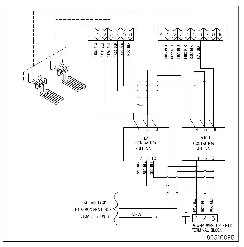
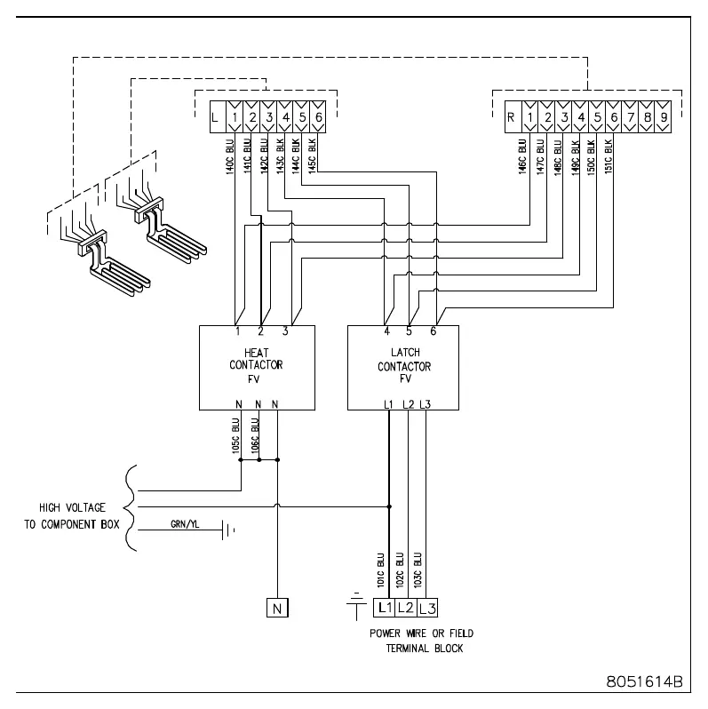
This document provides the necessary electrical schematics for the 1814E with FilterQuick series electric fryer. Ensure you are referencing the correct diagram for your specific installation configuration.

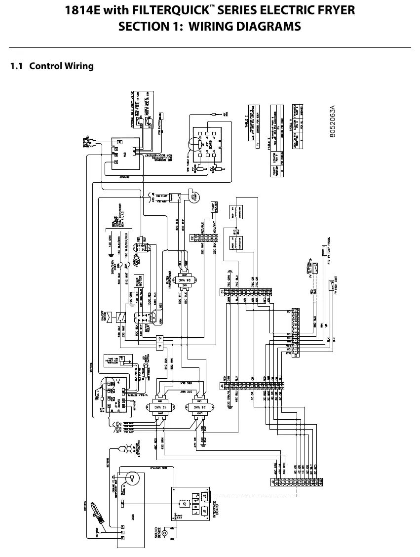
- Control Wiring: Detailed schematic for the main control board and interface connections.
- Contactor Box – Delta Configuration: Wiring diagram for units configured for Delta power supply.
- Contactor Box – WYE Configuration: Wiring diagram for units configured for WYE power supply.
Technical Support
For further assistance, contact Frymaster at 800-551-8633 or 318-865-1711. You can also visit www.frymaster.com or email [email protected].
Official resources from the manual
Manufacturer information
Frymaster
Practical help
Common problems
Always disconnect all electrical power from the fryer before performing any movement, testing, or repair.
Verify if your installation requires Delta or WYE configuration and use the corresponding diagram provided in this manual.
Before use
- Verify that the power supply matches the fryer's electrical configuration.
- Ensure all electrical connections are secure and match the provided schematics.
- Disconnect all power before opening the contactor box or control panel.

Manual page author
David Miller
Documentation analyst
Organizes user manual content into clear summaries, with attention to model details, product context, and everyday usability.