Sports / Bicycle Components
User Manual for 20k Scanner Set
Comprehensive user guide for the 20k scanner set laser driver board. Includes instructions for potentiometer adjustments, DMX channel mapping, menu navigation, and technical specifications.
Quick answers from the manual
Quick answer
- The 20k scanner set is a laser driver board. Use the menu buttons (Function, Confirm, Up, Down) to configure settings like auto speed, DMX address, and laser type. Refer to the DMX channel table for control mapping. p. 1, 5, 6
Key actions
- Reset the device p. 8
- Set DMX address p. 5
First start
- Power on and verify LED p. 5
Show 4 more answers Show less
Problems and fixes
LED not lighting up
Press any key to return to the current menu.
p. 5Maintenance and reset
- Reset and initialize all parameters p. 8
Technical specifications
| Parameter | Value | Meaning | Pages |
|---|---|---|---|
| Voltage | +15V/1.0A, -15V/0.5A | Power supply requirements | p. 1 |
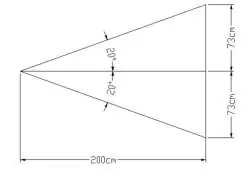
| Scan angle | ±20° | Maximum scanning range | p. 1 |
| Working temperature | 0-50°C | Operating environment | p. 1 |
Where to find it in the PDF
- Potentiometer and Features p. 1
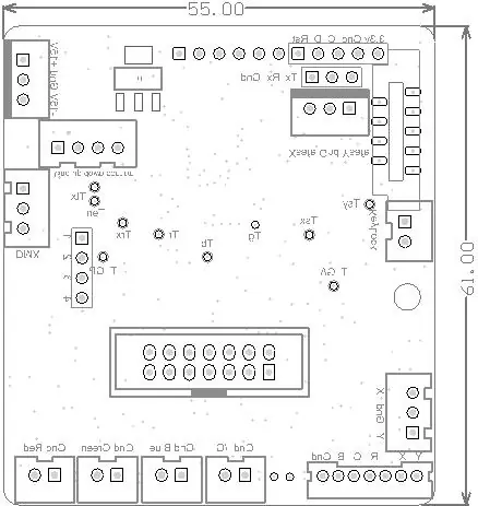
- Board Layout p. 2
- DMX Channel Mapping p. 3, 4
- Menu Operation p. 5, 6, 7, 8
Table of contents
Manual images
Click an image to enlargeQuick guide from the manual
This document provides instructions for the 20k scanner set laser driver board. Key operations include configuring the DMX address, adjusting laser parameters via the menu, and understanding the potentiometer settings. Always ensure the power supply is correct (+15V/1.0A, -15V/0.5A) before operation.
Potentiometer description
The board features several potentiometers for fine-tuning. Note that these are not marked on the board. Warning: Do not change the PS (Position scale) setting as it affects input sensitivity.
- IS: Input scale (adjusted only in factory).
- SG: Servo gain (power of the feedback signal for internal PID controller).
- LFD: Low frequency damping (correct overshoot).
- HFD: High frequency damping (correct undershoot).
- LIN: Zero offset (electrical offset of the driver, adjusted only in factory).
- PS: Position scale (increases or decreases input sensitivity of the computer).
Menu operation
Use the Function, Confirm, Up, and Down buttons to navigate the menu. Pressing 'Confirm' enters edit mode. Settings are stored automatically.
- Axxx: Auto speed (default 10, range 1-49).
- Sxxx: Delay time or sound-activated speed (default 5, range 1-50).
- dxxx: DMX address code (range 1-512).
- Lxxx: Beam and animation selection.
- Vxxx: Version number.
- Ixxx: Automatic switching (0=off, 1=on).
- n.xxx: XY direction settings (1-8).
- xCxx: DMX channel configuration (default 18, switchable to 27).
DMX Channel Mapping
The scanner supports various DMX channels for controlling laser effects, including:
- Channel 1: Mode selection (Laser OFF, Sound mode, Auto mode, Cartoon/Pattern).
- Channel 2: Color selection (Fixed color, 7 color, Palette).
- Channel 3: Pattern selection.
- Channel 4-5: Manual/Auto movement (Vertical/Horizontal).
- Channel 6-7: Rolling-over effects.
- Channel 8: Rotation.
- Channel 9: Zoom.
- Channel 10: Size.
- Channel 11: Show/Segmentation.
- Channel 12: Drawing selection.
Reset Procedure
To reset and initialize all parameters, press the 'Confirm' key for 3 seconds.
Official resources from the manual
Practical help
Common problems
LED does not light up
Press any key to return to the current menu.
DMX console not functioning properly
Check if RDM is enabled (rdnn setting). Some consoles may not function correctly when RDM is enabled.
Single point laser issue
Ensure the figure size is not set to 0. The minimum value is 2 to prevent security problems.
Before use
- Verify power source: +15V/1.0A and -15V/0.5A.
- Check working temperature range: 0-50°C.
- Ensure the DMX signal is connected if using DMX control mode.
- Identify the potentiometers on the board before attempting any tuning.
Show more Show less
Specs in practice
- Mirror reflex
- >99% @45° (length: 400nm-680nm)
- Drive board size
- 77.2mm x 58mm x 27.5mm
Images and diagrams
- The board layout diagram shows the location of power inputs, DMX ports, and signal connectors.
- The test method diagram illustrates the scan angle and test standard distance.
Model compatibility
- Standard version supports 18 DMX channels, switchable to 27 channels.
- Compatible with ILDA_user software for updating play lists.

Manual page author
Michael Turner
Technical manual editor