Automotive / Electrical Accessories
User Manual for Generic Car Switch
Quick guide for the Generic Car Switch. Includes installation steps, wiring diagrams, safety warnings, and technical specifications for 12V vehicle systems.
Quick answers from the manual
Quick answer
- This is a 12V DC car switch. It requires a relay for high-power devices and must be installed by disconnecting the battery first. p. 1, 2
Key actions
- Disconnect the negative terminal of the car battery before installation. p. 1, 2
- Use a relay for high-power devices. p. 1
First start
- After wiring, reconnect the battery and toggle the switch to test the LED indicator and device function. p. 2
Problems and fixes
Switch becomes loose, hot, smelly, or noisy
Stop using it immediately and check or replace it.
p. 2Technical specifications
| Parameter | Value | Meaning | Pages |
|---|---|---|---|
| Input Voltage | DC 12V | Vehicle power supply | p. 1 |
| Rated Current | 1.5A | Maximum current limit | p. 1 |
| Rated Power | 18W | Maximum power capacity | p. 1 |
Where to find it in the PDF
- Product Overview and Safety p. 1
- Installation and Usage p. 2
- Wiring Diagram p. 3
Table of contents
Quick Guide
This manual provides instructions for installing and operating the Generic Car Switch. Important: This device is designed exclusively for 12V DC vehicle power systems. Do not connect to 220V AC household power. Always disconnect the negative terminal of the car battery before beginning installation to prevent short circuits or electric shock.
Product Overview and Specifications
The device is a dual-switch unit designed for automotive modification. It features a flame-retardant ABS construction.
- Input Voltage: DC 12V
- Rated Current: 1.5A
- Rated Power: 18W (Max)
- Working Temperature: -10°C to 60°C
Note: Do not exceed the rated current. High-power devices such as lights, air pumps, or light bars must be used with a relay to avoid overheating and damaging the switch.
Safety Instructions
- Disconnect the negative terminal of the car battery before installation.
- Ensure all wiring is firm and well-insulated using heat-shrink tubing or electrical tape.
- Exposed metal is strictly prohibited to prevent short circuits and fire.
- Ensure the waterproof gasket is correctly installed and compressed during installation.
- Keep the switch away from high-temperature, oil, and water areas.
- Do not disassemble or modify the internal structure of the switch.
- If the switch becomes loose, hot, smelly, noisy, or abnormal, stop using it immediately.
Installation and Wiring
Preparation: Ensure you have the necessary tools, including a screwdriver, wire stripper, heat-shrink tubing or electrical tape, and a hole punch.
Drilling and Installation:
- Replace the blank reserved switch directly or select a suitable position and drill accurately.
- Insert the switch from the front of the panel.
- Install the waterproof gasket on the back, ensuring no deviation.
- Install the washer and mounting nut in sequence.
- Tighten moderately with a screwdriver to ensure the switch is stable and the gasket is fully compressed.
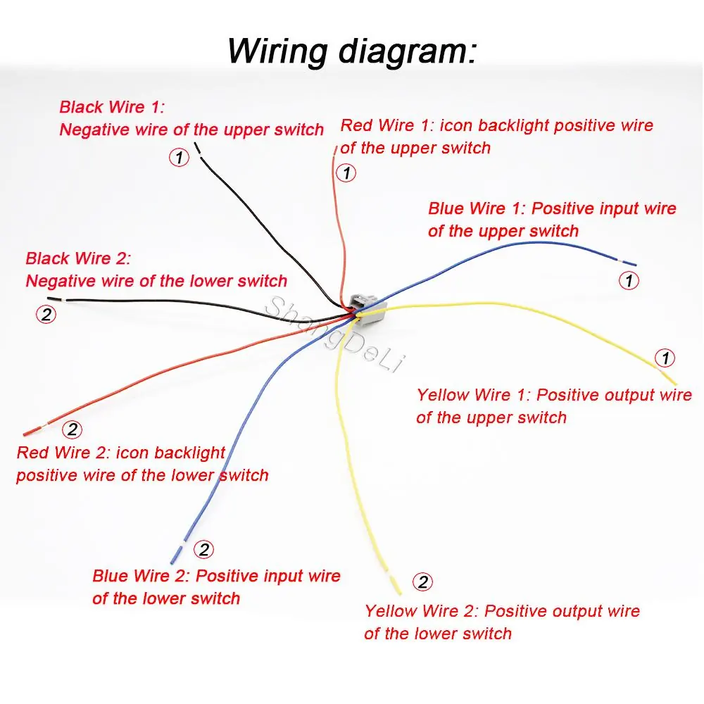
Wiring: Distinguish between positive and negative poles to avoid reverse connection. Refer to the wiring diagram for specific color-coded connections for the upper and lower switches. Wrap all connectors with heat-shrink tubing or electrical tape.
Testing and Finishing
After wiring, perform the following steps:
- Check that all connections are firm, with no exposed wires or reverse polarity.
- Reconnect the negative terminal of the battery.
- Toggle the switch to test the LED indicator and the connected electrical device.
- Check for overheating, abnormal noise, or other abnormalities.
- Organize wires and fix the excess harness with cable ties to prevent winding and wear.
- Paste function labels for easy identification.
- Verify that the switch is securely installed and the waterproof gasket is properly sealed.
Practical help
Common problems
Switch becomes hot, smelly, or noisy
Stop using the switch immediately and check or replace it.
High-power device failure or switch overheating
Ensure a relay is used for high-power devices (lights, air pumps, etc.); do not drive heavy loads directly.
Waterproofing failure
Ensure the waterproof gasket is correctly installed, not deviated, and fully compressed during installation.
Before use
- Disconnect the negative terminal of the car battery.
- Verify the power supply is 12V DC.
- Prepare tools: screwdriver, wire stripper, heat-shrink tubing/electrical tape, hole punch.
- Check that all accessories are complete and intact.
- Ensure the installation area is free from high temperature, oil, and water.
Specs in practice
- Input Voltage: 12V DC
- Compatible only with 12V vehicle power. Do not connect to 220V AC.
- Rated Current: 1.5A
- Maximum current capacity of the switch. Use a relay for higher loads.
- Rated Power: 18W
- Maximum power capacity of the switch.
Images and diagrams
- The wiring diagram details the specific color-coded wires for both the upper and lower switches.
- Yellow wires are for positive output.
- Blue wires are for positive input.
- Red wires are for icon backlight positive.
- Black wires are for negative connections.
Model compatibility
- Designed for 12V DC vehicle systems only.
- Not suitable for 220V AC household power.

Manual page author
Emily Carter
User documentation editor
Prepares concise manual descriptions and highlights the most useful setup, operation, and maintenance information for readers.