Industrial / Access Equipment
Installation Guide for Genie 105295-HEI Control System Kit
Installation and configuration guide for the Genie 105295-HEI control system kit. Includes step-by-step installation procedures, software configuration, machine settings, and speed tuning instructions for various Genie models.
Table of contents
Manual images
Click an image to enlargeQuick guide from the manual
This document provides installation and configuration instructions for the 105295-HEI Control System Kit. It is intended for qualified service professionals. Before beginning, ensure the machine is on a solid, level surface with the platform in the stowed position. The procedure requires basic tools including a #2 slotted screwdriver, 11/32 inch and 7/16 inch combination wrenches, and dielectric grease.
Installation Procedures
The installation process varies slightly depending on the specific kit and machine model. General steps include:
- Tag and disconnect the platform controls wire harness from the control cable at the platform main deck.
- For models with a foot switch, disconnect the harness from the foot switch.
- Remove the existing platform controls and the catch bracket.
- Install the new platform controls mount and secure the catch bracket using the provided fasteners.
- Install the new platform controls onto the mount.
- Connect the wire harness to the control cable and foot switch (if applicable) using dielectric grease in the connectors.
- For specific kits, install the provided decal and harness adapter as instructed.
Changing the Software Configuration
To enter the software configuration mode:
- Pull out the red Emergency Stop button at the ground controls.
- Push in the red Emergency Stop button at the platform controls.
- Turn the key switch to platform control.
- Press and hold the lift function select and speed select buttons, then pull out the red Emergency Stop button at the platform controls. The diagnostic display will show SC.
- Release the buttons to view the current configuration.
- Use the lift function select button to adjust the tens digit and the speed select button to adjust the ones digit, using the steering thumb rocker switch to change values.
- Turn the key switch to the off position to save settings.
Speed Tuning
To adjust lift or drive speeds:
- Follow the same initial steps as the software configuration to enter the mode, but press the lift function select and horn buttons while pulling out the red Emergency Stop button.
- The diagnostic display will show PS.
- Press the specific function button (lift, drive, or slow speed select) to view the current percentage.
- Use the steering thumb rocker switch to increase or decrease the speed percentage.
- Turn the key switch to the off position to save changes.
Machine Configurations
The manual provides detailed configuration code charts for various Genie models (GS-1530, GS-1532, GS-1930, GS-932, GS-2032, GS-2632, GS-2046, GS-2646, GS-3246). These charts map diagnostic display codes to specific machine options such as Motion Beacon, Motion Alarm, Lift/Drive Cut Out, Platform Overload, and Descent Delay.
Manufacturer information
Genie
Practical help
Common problems
Diagnostic display shows 'SC'
The system is in Software Configuration mode. This is normal when performing configuration procedures.
Battery drain alarm sounds
The alarm sounds if the machine is on and no function is activated for 10 minutes. This can be enabled or disabled in the software configuration settings.
Machine tipping hazard
Do not adjust lift or drive speeds higher than specified in the manual. Only trained service professionals should perform speed adjustments.
Before use
- Ensure the machine is on a solid, level surface.
- Place the platform in the stowed position.
- Verify you have a #2 slotted screwdriver.
- Verify you have 11/32 inch and 7/16 inch combination wrenches.
- Have dielectric grease ready for electrical connections.
- Ensure personnel are qualified to identify risks and hazards.
Specs in practice
- Diagnostic Display Code
- A numeric code used to identify and set machine configuration options.
- DIP Switch Code
- Binary representation used to configure specific machine features.
- Lift/Drive Cut Out
- Safety feature that disables lift and drive functions when the machine exceeds rated capacity.
- Descent Delay
- Safety feature that halts descent at approximately 7 feet (2.1 m) for 4-6 seconds.
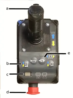
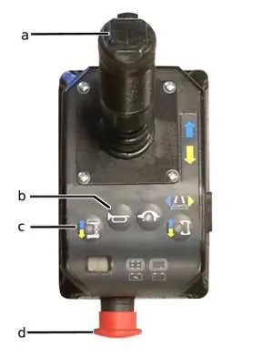
Images and diagrams
- The joystick controller diagram identifies the thumb steering rocker, lift function select button, diagnostic display, red emergency stop button, and speed select button.
Model compatibility
- Compatible with GS-1530/1532/1930/1932 (before S.N. 75000).
- Compatible with GS-2032/2632 (before S.N. 75000).
- Compatible with GS-2046/2646/3246 (before S.N. 75000).
- Compatible with GR-12/15/20 (after GR05-4999).

Manual page author
David Miller
Documentation analyst
Organizes user manual content into clear summaries, with attention to model details, product context, and everyday usability.