Home Appliances / Washing Machines
Genie 1294905GT Lift Connect Telematics Ready Connector Service Manual Supplement
A comprehensive service manual supplement for the Genie Lift Connect Telematics Ready Connector, covering wiring pinouts, I/O specifications, and safety requirements for various Genie equipment models.
Table of contents
Manual images
Jump to the sectionQuick guide from the manual
This document serves as a technical supplement for installing and connecting telematics devices to Genie equipment. It provides essential wiring pinouts, I/O specifications, and safety requirements for both current 12-pin and legacy 8-pin connector systems. Always verify the specific model requirements before installation, as some circuits may not be available on all machines.
Safety Rules
Telematics devices must be installed in compliance with local wireless carrier certifications (PTCRB, FCC/IC in North America; CE, RED 2014/53/EU in Europe). Owners are responsible for ensuring RF safety compliance and training personnel on potential radio frequency exposure hazards. Important: Telematics devices are not approved for use on Genie models with an EE rating; installation on such machines will invalidate the EE rating.
Telematics I/O Specifications
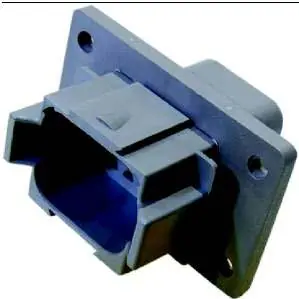
Genie machines manufactured from 2019 onwards feature a 12-pin Deutsch DT series panel mount or in-line receptacle. OEM suppliers should equip their devices with a matching 12-pin Deutsch plug. For models produced between 2015 and 2019, an 8-pin legacy connector may be present, requiring an adapter harness (Genie part number 1295251GT) to interface with 12-pin telematics devices.


Connector Pinouts and Functionality
The manual provides detailed I/O maps for various Genie product lines, including Slab Scissor, Z-Boom, S-Boom, and GTH models. Each pinout defines the circuit type (System Power, Digital Output, Digital Input, Databus) and its specific machine function (e.g., engine run monitoring, key switch activation, platform stowed status). Note that if a specific circuit feature is not supported by a model, the corresponding pin must be left unconnected.
Technical Support
For parts, tools, or technical assistance, contact Genie Parts Sales via the following channels:
- Website: www.genielift.com
- Phone: (877) 367-5606
- Email: [email protected]
Official resources from the manual
Manufacturer information
Genie
Practical help
Common problems
Telematics device not functioning on older machines
Check if the machine uses the legacy 8-pin connector. You may need an adapter harness (Genie p/n 1295251GT) to connect a 12-pin device.
Circuit feature not working
Verify if your specific Genie model supports the discrete output. If the feature is not available on your model, it must be left unconnected.
EE rating invalidation
Do not install telematics devices on Genie models equipped with an EE rating, as this will invalidate the machine's safety rating.
Before use
- Verify the machine model year to determine if a 12-pin or 8-pin connector is installed.
- Ensure the telematics device complies with regional wireless certifications (FCC/IC or CE).
- Check the specific TRC Function Pin Out for your machine model.
- Confirm the machine does not have an EE rating before proceeding with installation.
- Ensure all personnel are trained on potential RF exposure hazards.
Specs in practice
- System Power (Pin 1)
- Provides constant battery power (12V or 24V depending on model). Max allowed draw is 5 Amps.
- Digital Output 1 (Pin 4)
- Typically monitors engine run hours or DC motor controller status.
- Digital Input 1 (Pin 7)
- Used for the Remote Machine Disable feature via an active low relay.
- Databus H/L (Pins 11/12)
- CAN/J1939 communication lines for receiving proprietary Genie telematics messages.
Images and diagrams
- The manual includes specific pinout diagrams for different machine families (e.g., GS, Z-Boom, S-Boom, GTH).
- Remote Disable relay configuration diagrams show the connection between the ignition/foot switch input, the relay, and the telematics active low input.
Model compatibility
- 12-pin connector is standard on machines from 2019 onwards.
- 8-pin connector is standard on legacy machines (2015-2019).
- Adapter harness 1295251GT is required to connect 12-pin devices to 8-pin machines.

Manual page author
Michael Turner
Technical manual editor
Reviews PDF manuals for structure, safety notes, and practical product details so readers can find the right information quickly.