Home Appliances / Cooktops Hobs
User Guide for Hobbywing 110A Electronic Speed Controller
Comprehensive user guide for the Hobbywing 110A 4-in-1 Electronic Speed Controller, covering wiring, startup procedures, and configuration settings.
Table of contents
Manual images
Jump to the sectionProduct Overview
The Hobbywing 80A-4in1-Lite-AT is a high-performance electronic speed controller (ESC) designed for FPV drones and multirotors. It features a continuous current rating of 80A and a peak current of 100A (for 10 seconds). The unit is compatible with 4-8S LiPo batteries and weighs 41.3g.
Wiring and Installation
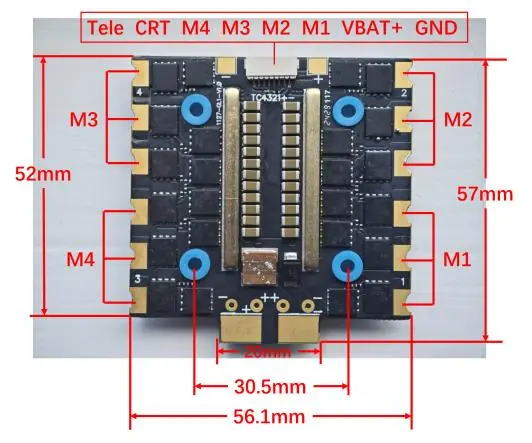
The ESC features dedicated pads for motor connections (M1-M4) and flight controller integration. Ensure correct polarity when connecting the battery (VBAT+ and GND). The board layout includes specific pads for telemetry (Tele) and control signals (CRT). Refer to the provided wiring diagrams for precise pinout locations to ensure proper communication between the flight controller and the ESC.
Startup Procedure
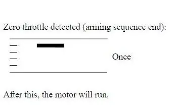
The ESC follows a standard arming sequence. Upon power-up, the system detects the throttle signal. Once zero throttle is detected, the arming sequence completes, and the motors are ready to run.
Configuration and Software
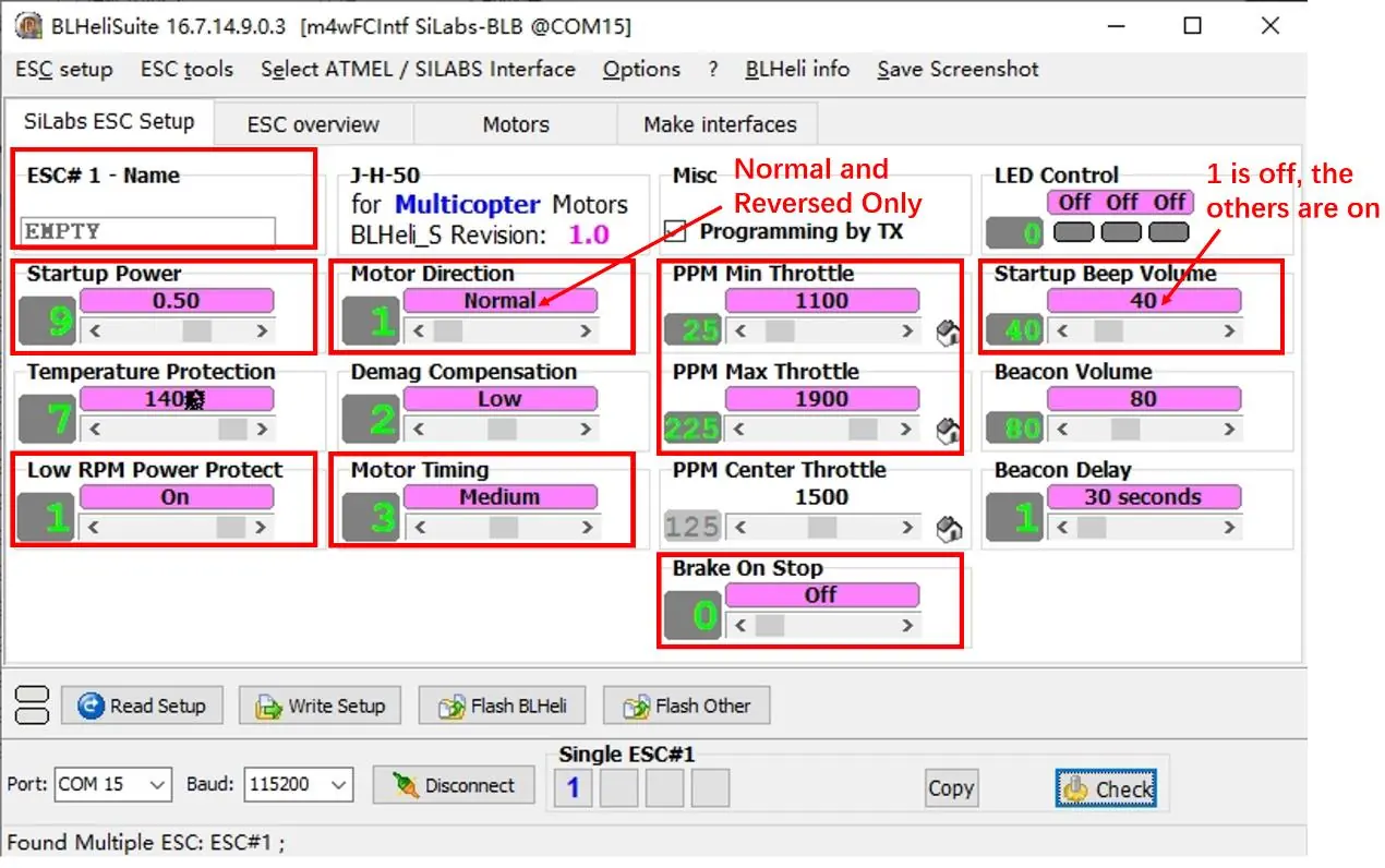
This product utilizes self-developed firmware. Note that BLHeli_32 is currently unavailable due to the closure of the BLHeli company. Users can manage settings via BLHeliSuite16xx. Configuration parameters include motor direction, startup power, temperature protection, and throttle range settings. Detailed documentation for adjustable parameters can be found in the official BLHeli_S SiLabs manual.
Important Notes
The ESC does not include a built-in BEC (Battery Eliminator Circuit). Ensure your flight controller or external power source provides the necessary voltage for your receiver and peripherals. Always verify your firmware version and compatibility before attempting to flash or update the ESC settings.
Manufacturer information
Hobbywing
Practical help
Common problems
ESC not arming
Ensure the throttle is at zero position during startup. Check that the flight controller is sending a valid zero-throttle signal.
BLHeli_32 software incompatibility
This device uses self-developed firmware; use BLHeliSuite16xx for configuration instead of BLHeli_32.
Before use
- Verify battery voltage is within the 4-8S LiPo range.
- Check all motor connections (M1-M4) for secure soldering.
- Confirm the flight controller signal wires are connected to the correct pads.
- Ensure no short circuits exist between VBAT+ and GND pads.
- Download and install the compatible BLHeliSuite16xx software.
Specs in practice
- Cont. Current 80A
- The maximum current the ESC can handle continuously without overheating.
- Peak Current 100A
- The maximum current the ESC can handle for short bursts (up to 10 seconds).
Images and diagrams
- The wiring diagram shows the specific pads for M1, M2, M3, and M4 motor connections.
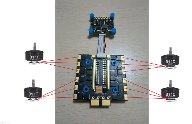
- The FC-ESC wiring diagram illustrates the connection path between the flight controller and the ESC board.
- The software interface screenshot highlights key adjustable parameters like motor direction, startup power, and throttle range.
Model compatibility
- Compatible with 4-8S LiPo batteries.
- Requires BLHeliSuite16xx for parameter adjustments.
- Not compatible with BLHeli_32 firmware.

Manual page author
David Miller
Documentation analyst
Organizes user manual content into clear summaries, with attention to model details, product context, and everyday usability.