Electronics / Cameras
User Manual for HuddleCamHD 10X-GY-G3 PTZ Camera
Quick guide for the HuddleCamHD 10X-GY-G3 PTZ camera. Includes installation steps, connection diagrams, OSD menu settings, and troubleshooting tips.
Table of contents
Manual images
Click an image to enlargeQuick guide from the manual
This document provides essential instructions for the HuddleCamHD 10X-GY-G3 PTZ camera. Key operations include connecting the camera via USB 3.0, configuring the OSD menu for image adjustments, and performing physical installations such as desktop, tripod, or ceiling mounting. Always ensure the camera is on a level surface or within a 15-degree incline for proper operation.
Safety Precautions
- Read the manual carefully before use.
- Avoid stress, vibration, or liquid intrusion during transport and installation.
- Do not apply excessive voltage; use only the supplied power adapter.
- Keep away from strong electromagnetic sources.
- Do not aim the camera at bright light sources (e.g., sun) for extended periods.
- Do not disassemble the camera; contact an authorized dealer for repairs.
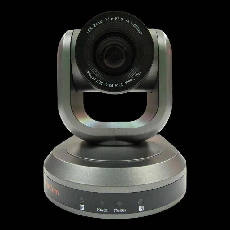
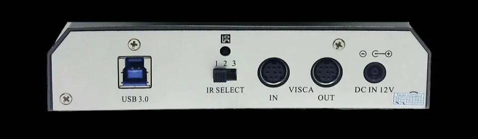
Physical Description
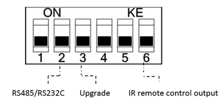
The camera features a lens, IR receivers, and status LEDs on the front. The rear panel contains the USB 3.0 interface, IR selective switch, RS232/RS485 control ports, and the DC 12V power socket. The bottom includes a dip-switch for hardware settings and a tripod mount.
Dip-Switch Settings
Ensure the camera is powered off before changing dip-switch settings. The switches control the communication protocol (RS-485/PELCO-D vs. RS-232/VISCA), firmware upgrade mode, and IR remote control output.
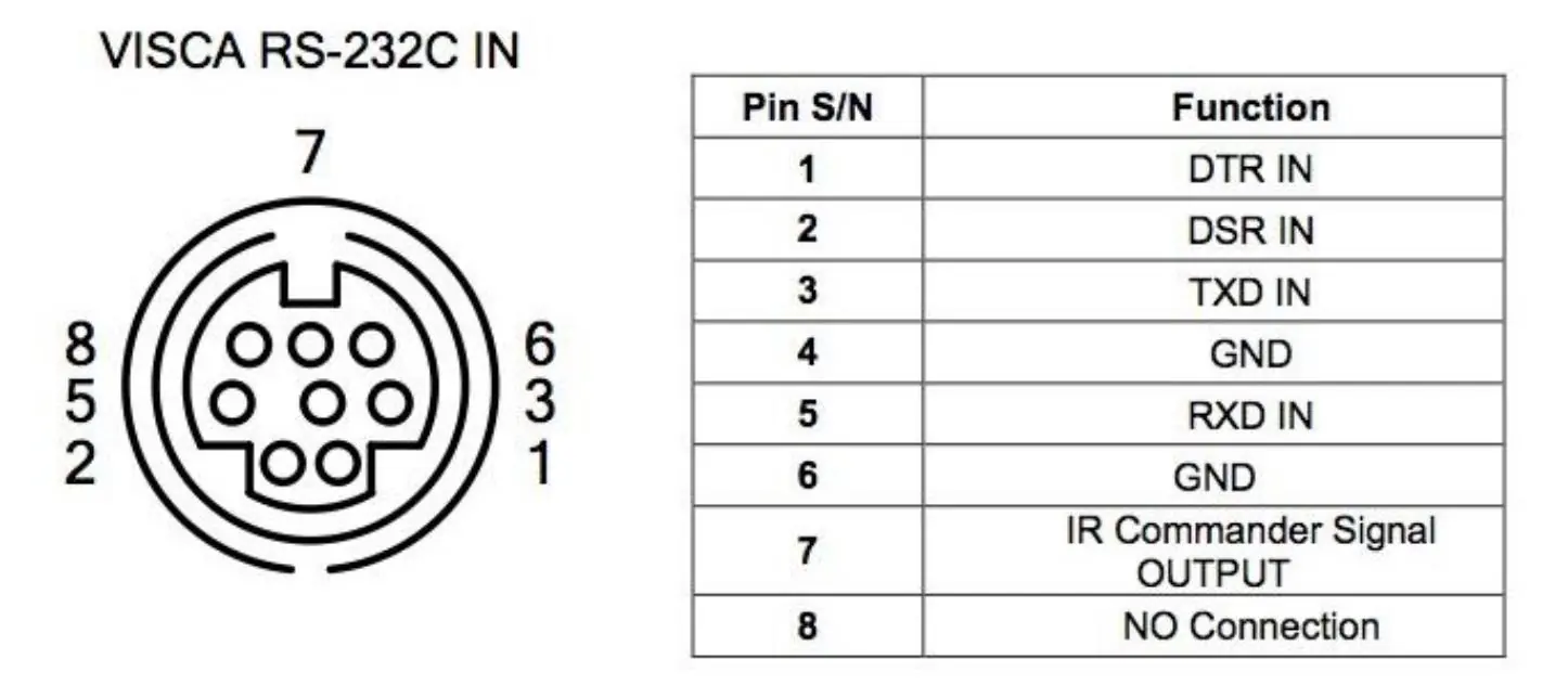
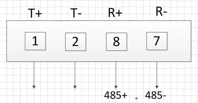
Cable Connection
The camera supports RS-232 and RS-485 control. Refer to the specific pinout diagrams for VISCA RS-232C IN and OUT connections to ensure proper communication with third-party controllers.
OSD Menu
The On-Screen Display (OSD) menu allows for advanced configuration. Note that you cannot manually move the camera (pan/tilt) while the OSD menu is visible. Settings include protocol, baud rate, pan/tilt speeds, exposure, color, and image orientation.
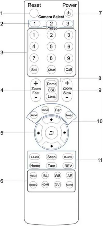
IR Remote Controller
The remote allows for camera selection (1-3), preset management, manual pan/tilt/zoom control, and access to the OSD menu. Use the 'Set', 'Clear', and 'Call' buttons to manage preset positions.
Installation Instructions
Desktop Installation: Ensure the camera stands level. If using an incline, the angle must be less than 15 degrees.
Tripod Installation: Screw the tripod into the bottom of the camera using a 1/4-20 bolt (5-7mm length).
Ceiling Mount: Follow the 4-step process: secure the ceiling plate, fix the triangle plate to the camera, connect the triangle plate to the ceiling plate, and lock the set screws.
Troubleshooting
- No power: Check power adapter connections and ensure the power switch is ON.
- No USB connection: Try a new USB cable. Connect the camera to the PC only after it has fully booted.
- Remote not working: Ensure the 'Camera Select' button on the remote matches the 'IR Select' switch on the camera.
- Cannot pan/tilt/zoom: Exit the OSD menu first.
USB Connectivity Notes
The camera uses UVC drivers built into Windows, Mac OS, and Linux. Avoid using external USB hubs for reliable HD video transmission. Ensure USB 3.0 power-saving settings in the OS are turned off.
Specifications
- Sensor: 1/2.8” CMOS 2.1 Mega Pixel
- Zoom: 10X Optical Zoom
- Video Interface: USB 3.0
- Pan/Tilt: 0-359° Pan, Up 90°/Down 45° Tilt
- Power: 12V DC 2A
Practical help
Common problems
No power to the camera
Check connections between the camera, power adapter, and mains. Ensure the power switch is set to ON.
Camera will not connect to PC via USB
Try a new USB cable. Connect the USB cable only after the camera has completely booted.
Camera unable to pan, tilt, or zoom
Ensure the OSD menu is not displayed on the screen. Check if the pan/tilt/zoom range limit was reached.
Remote control not working
Ensure the 'Camera Select' button on the remote matches the 'IR Select' switch number set on the camera.
Before use
- Connect the included power supply to the camera.
- Wait for the camera to complete its home position movement.
- Connect the included USB 3.0 cable to the camera and the PC.
- Ensure the camera is placed on a level surface (or <15° incline).
- Select and configure the camera in your software of choice.
Specs in practice
- Video Interface
- USB 3.0 (backwards compatible with USB 2.0)
- Pan Movement
- 0-359° rotation range
- Tilt Rotation
- Up: 90°, Down: 45°
Images and diagrams
- Front View: Identifies lens, IR receivers, and status LEDs.
- Rear View: Identifies USB 3.0, IR Select, RS232/RS485 ports, and DC power input.
- Dip-Switch: Shows settings for control protocol and IR remote output.
- Ceiling Mount: Illustrates the 4-step installation process using the triangle bracket.
Model compatibility
- USB 3.0 ports are backwards compatible with USB 2.0 devices.
- Avoid external USB hubs for reliable HD video transmission.
- Requires UVC (USB Video Class) drivers, which are built into Windows, Mac OS, and Linux.

Manual page author
Michael Turner
Technical manual editor
Reviews PDF manuals for structure, safety notes, and practical product details so readers can find the right information quickly.