Industrial / Control Switches
IDEC XA/XW Series Emergency Stop Switch User Guide
A comprehensive user guide for IDEC XA/XW series emergency stop switches. Includes installation, wiring, technical specifications, and safety compliance information for 16mm and 22mm models.
Quick answers from the manual
Quick answer
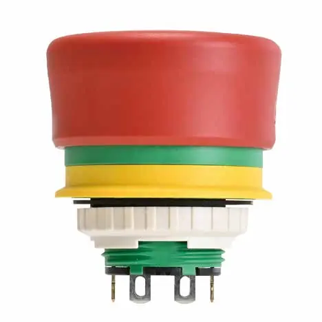
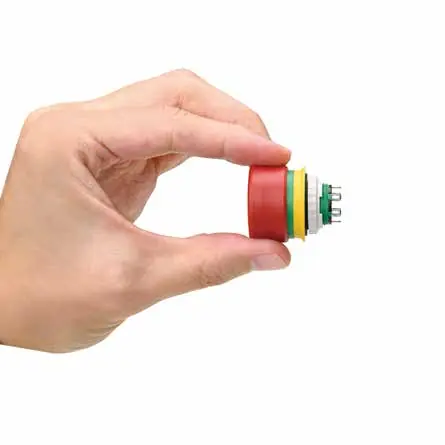
- The IDEC XA/XW series are compact, unibody emergency stop switches with a 12.6mm panel depth, designed for industrial safety applications. p. 2
Key actions
- Mounting involves inserting the operator into the panel hole and tightening the locking ring with the specified wrench. p. 11
First start
- Ensure the rubber gasket is installed, align the protrusion with the panel groove, and tighten the locking ring to the specified torque. p. 11
Problems and fixes
Contact chatter/bounce
Take countermeasures to prevent chatter/bounce (Reference value: 20ms) and do not apply external shock.
p. 11Maintenance and reset
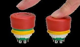
- Reset the switch by pulling or turning clockwise. p. 8
Technical specifications
| Parameter | Value | Meaning | Pages |
|---|---|---|---|
| Operating temperature | -25 to +70°C | Operating range for non-illuminated type. | p. 7 |
| Degree of Protection | IP65, IP67, IP69K, UL Type 4X | Protection against dust and water. | p. 7 |
Where to find it in the PDF
- Features p. 2, 3
- Installation p. 11
- Technical Specifications p. 7
Table of contents
Manual images
Click an image to enlargeQuick guide from the manual
The IDEC XA/XW series are compact, unibody emergency stop switches designed for industrial safety. They feature a minimal panel depth of 12.6mm, reverse energy structure, and are compliant with ISO13850:2015 standards. This guide covers installation, wiring, and maintenance.
Panel mounting
To install the switch:


- Remove the locking ring from the operator.
- Ensure the rubber gasket is in place.
- Insert the operator from the front of the panel into the panel hole.
- Align the protrusion on the operator with the groove in the panel hole.
- Install the locking ring and tighten using the appropriate wrench (MT-001 for XA series, MW9Z-T1 for XW series).
- Tightening torque: 0.8 to 0.9 N·m for XA series; 1.8 to 2.0 N·m for XW series.
Wiring
Follow these guidelines for wiring:
- Wire size: 1.25mm² maximum.
- Soldering: Use a soldering iron at 310 to 350°C for a maximum of 3 seconds. Face terminals downward to prevent flux from entering the switch.
- Protection: Use protective tubes or heat shrink tubes to prevent short circuits between poles.
- Force: Apply force to terminals only in the vertical direction to the panel to avoid damage.
Safety and operation
The switch is designed for intentional human action. The NC contact does not move until the switch latches, ensuring safety. The indicator (green area) allows for status checks at a glance. The switch is UL Type 4X certified for use in wet, windy, and snowy environments, though not all outdoor conditions are covered.
Technical specifications
- Operating temperature: -25 to +70°C (non-illuminated), -25 to +55°C (illuminated).
- Degree of protection: IP65, IP67, IP69K, UL Type 4X.
- Operating force: Pushlock 20N, Pull reset 12N, Turn reset 0.2N·m.
- LED life: 60,000 hours (at 25°C).
Maintenance and troubleshooting
Turn off power before any maintenance. Do not disassemble or modify the switch. If contact chatter occurs, ensure proper wiring and avoid external shocks. The LED lamp is built into the contact block and cannot be replaced.
Practical help
Common problems
Contact chatter/bounce
Ensure proper wiring and avoid external shock. Countermeasures (20ms) may be needed.
Short-circuit between poles
Use protective tubes or heat shrink tubes on terminals.
Resin discoloration
Avoid leaving the switch in high-temperature environments.
Before use
- Check that the rubber gasket is in place.
- Verify panel thickness is between 0.8 and 3.7mm.
- Ensure wire size is 1.25mm² maximum.
- Confirm ambient temperature is within specified limits.
- Verify the locking ring is tightened to the correct torque.
Specs in practice
- Degree of Protection
- IP65, IP67, IP69K, and UL Type 4X rated.
- Operating force
- Pushlock: 20N, Pull reset: 12N, Turn reset: 0.2N·m.
Images and diagrams
- Terminal arrangement: Shows NC/NO contact positions for wiring.
- Panel cut-out: Dimensions for mounting hole (16.2mm or 22.3mm).
Model compatibility
- Not for use in all outdoor environments.
- Not for use with high-pressure water exceeding IPX5/IPX7/IPX9K specifications.
- Not for use where strong magnetic or electric fields are generated.

Manual page author
Michael Turner
Technical manual editor
Reviews PDF manuals for structure, safety notes, and practical product details so readers can find the right information quickly.