Spare Parts and Schematic Manual for Lincoln Electric Invertec 135S, 150S, 170S
Access the official spare parts list, assembly diagrams, and electrical schematics for Lincoln Electric Invertec 135S, 150S, and 170S welding machines. Essential for maintenance and repair.
Table of contents
Manual images
Click an image to enlargeQuick guide from the manual
This document serves as the official spare parts and electrical schematic manual for the Lincoln Electric Invertec 135S, 150S, and 170S welding machines. It is designed to assist technicians and users in identifying components, understanding machine assembly, and troubleshooting electrical connections.
Spare Parts Identification
To identify the correct spare parts for your machine, locate the Code Number on your machine's nameplate. Use the tables provided in the manual to cross-reference this Code Number with the corresponding Figure (A, B, or C) and the specific part numbers listed.
Assembly Diagrams
The manual includes exploded-view diagrams for each model to assist with disassembly and reassembly:
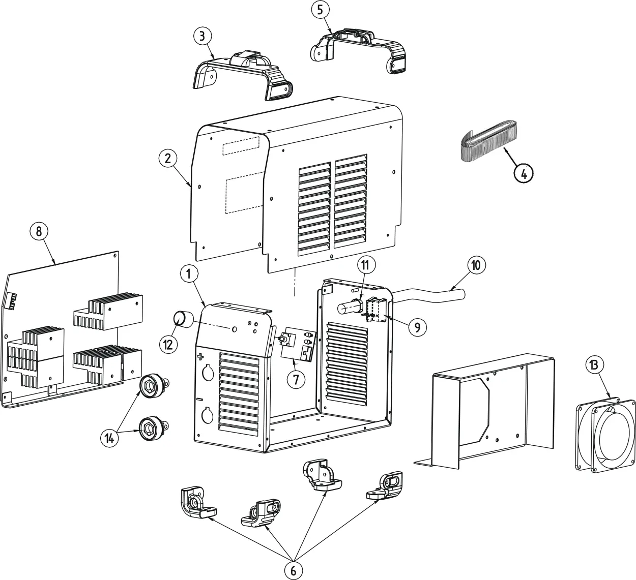
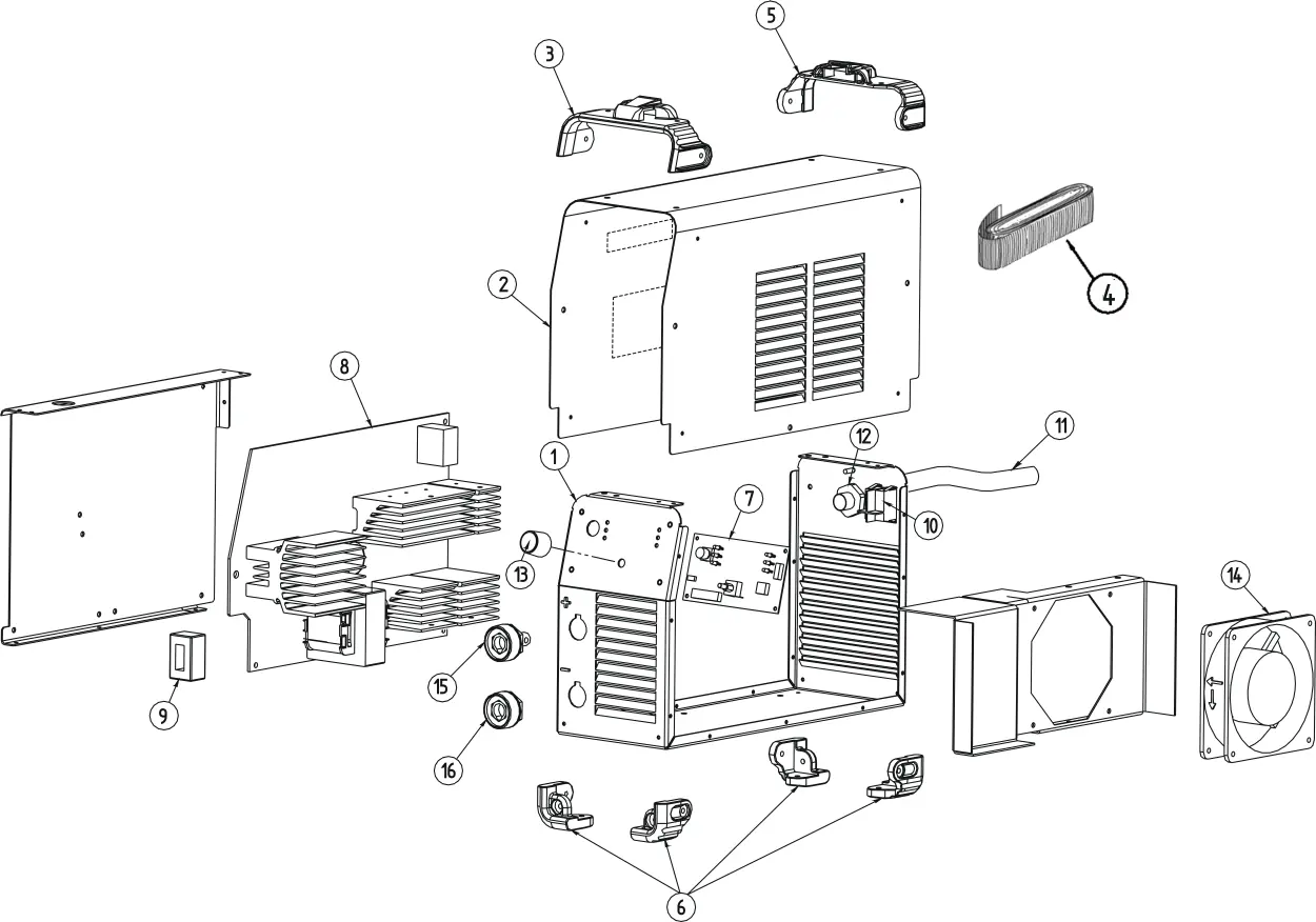

- Figure A: Machine Assembly for 135S.
- Figure B: Machine Assembly for 150S.
- Figure C: Machine Assembly for 170S.
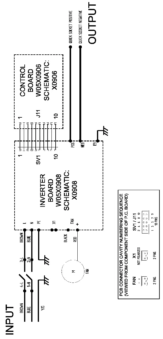
Electrical Schematics
Detailed electrical schematics are provided for each machine code to assist with electrical repairs and diagnostics. Ensure you refer to the schematic corresponding to your specific machine's Code Number.
Practical help
Common problems
Locate the Code Number on the machine's nameplate and match it with the table in the Spare Parts section.
Consult the specific electrical schematic provided for your machine's Code Number.
Before use
- Locate the machine's Code Number on the nameplate.
- Identify the correct assembly diagram (Figure A, B, or C) based on your model.
- Ensure the machine is disconnected from the power source before attempting any disassembly or repair.

Manual page author
David Miller
Documentation analyst
Organizes user manual content into clear summaries, with attention to model details, product context, and everyday usability.