Toys / RC Models & Drones
User Manual for mXion DGK 1-Channel Radio Feedback Module
Quick guide for the mXion DGK 1-Channel Radio Feedback Module. Learn how to install, connect, program via DCC, and troubleshoot your occupancy detector.
Table of contents
Manual images
Click an image to enlargeImportant Information
Before installing and operating the mXion DGK, read this manual thoroughly. Ensure the device is installed in a protected location and is not exposed to constant moisture. Some features may require the latest firmware; perform an update if necessary. Ensure output voltages are set correctly to avoid damaging connected devices.
Product Description
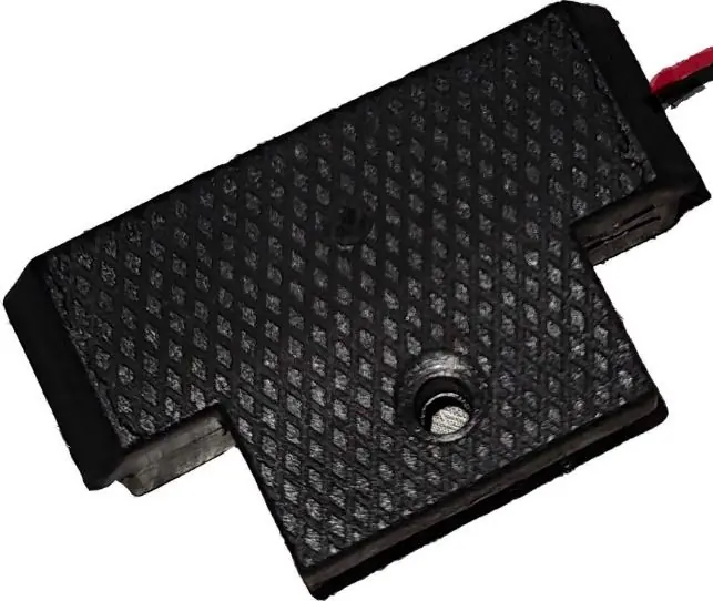
The mXion DGK is a universal, analog and digital occupancy detector designed for detecting electricity consumers within a section. It features fully encapsulated electronics, making it weather-proof and ideal for installation in LGB tracks. The module includes a full-fledged decoder and an integrated reed switch that can be triggered by a magnet. An integrated radio module allows for switching commands or feedback addresses to be sent to the control center, reducing the need for extensive cabling.
Installation and Connection
Installation is straightforward:
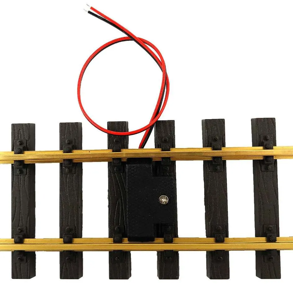
- Connect the two cables to the digital track.
- Place the DGK between the track and secure it firmly with the provided screw.
- Ensure that mounting screws or metal parts do not cause a short circuit.
- The module requires 2 seconds to start up after power is applied before it can be addressed via magnets.
Operation
The integrated reed switch is triggered by a train magnet. The module supports various modes, including occupancy reporting (Mode 2) for PC control, switch commands, and feedback. The radio channel must be identical to the one set in your central unit (MZSpro or 30Z). You can verify the radio module status via CV10.
Configuration and Programming
Settings are configured via DCC using a programming track or via POM (Programming on Main). The module supports CV programming (CV, Register, Bitwise, POM). Refer to the CV-Table in the manual for specific register values, such as setting the feedback address, delay times, and radio channel.
Technical Data
- Voltage: 7-27V DC/DCC or 5-18V AC
- Current: 20mA
- Temperature range: -20 to 80°C
- Dimensions: 1.4 x 4.5 x 3.5 cm
Note: If using the device below freezing temperatures, ensure it was stored in a heated environment before operation to prevent condensation.
Troubleshooting and Maintenance
If the device is not responding, wait 2 seconds after power-up. Ensure the radio channel matches your central unit. For technical support, contact micron-dynamics via email at [email protected] or [email protected].
Practical help
Common problems
Device not responding after power-up
Wait at least 2 seconds for the module to initialize before attempting to trigger it with a magnet.
Short circuit during installation
Ensure that mounting screws or nearby metal parts are not causing a short circuit with the module electronics.
Radio feedback not working
Verify that the radio channel on the DGK is identical to the channel set in your central unit (check CV10).
Before use
- Ensure the output voltage matches your consumer device.
- Verify the module is installed in a protected, dry location.
- Check for the latest firmware updates.
- Ensure the radio channel is identical to the central unit.
- Confirm the module is securely screwed into the track.
Specs in practice
- Temperature range
- Operational between -20°C and 80°C.
Images and diagrams
- The connection diagram illustrates the two cables connecting to the digital track.
- The sensor position diagram indicates where the reed switch is located for magnet triggering.
Model compatibility
- Compatible with all analog and digital systems.
- Designed for LGB tracks.
- Works with MZSpro and 30Z central units.

Manual page author
Emily Carter
User documentation editor
Prepares concise manual descriptions and highlights the most useful setup, operation, and maintenance information for readers.