Toys / Model Accessories
User Manual for mXion SWD-ED 1-Channel Servo Decoder
Comprehensive user guide for the mXion SWD-ED 1-Channel Servo Decoder. Includes installation instructions, wiring diagrams, operating modes, CV programming, and technical specifications for model railway servo control.
Table of contents
Manual images
Click an image to enlargeQuick Guide
The mXion SWD-ED is a compact 1-channel servo decoder designed for model railways. It supports both analog and digital (NMRA-DCC) operation. The device can control servos for various applications such as bells, signals, barriers, and cranes. It is programmable via CVs and supports both locomotive and switch addresses.
Product Description
The decoder features a dedicated connector for direct servo attachment. It can drive two servos symmetrically (e.g., for uncoupling). A separate switching output is integrated for lamps or other accessories. The decoder supports multiple specialized control modes, including bell swinging, rocking for signals/barriers, and rotary control for cranes.
Installation and Wiring
Install the device carefully according to the wiring diagrams. The electronics are protected against shorts and excessive loads, but improper wiring (e.g., shorted cables) can destroy the device. Ensure no short circuits occur with mounting screws or metal parts.
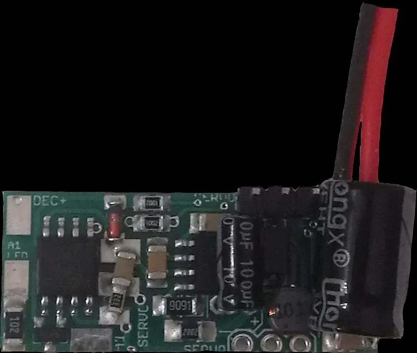

- Servo Connection: The servo plugs directly into the PCB.
- Servo Cable Colors: +5V is red, GND is brown or black.
- Power Supply: Connect to track power (Gleis/Track).
Operating Modes
The operating mode is set via CV115:
- 0: Normal function.
- 1: Bell swinging (realistic up and down motion).
- 2: Rocking for signals and barriers.
- 3: Control via rotary/speed steps (for cranes).
Additional parameters like speed, switching time, and end positions can be adjusted via specific CVs (e.g., CV103, CV104, CV113, CV114).
Programming and CVs
The decoder supports bitwise, POM, and register programming. To prevent accidental changes, use the programming lock (CV15/16). Only if CV15 equals CV16 is programming possible.
- Locomotive Address: Programmed in CV1 (or CV17/18 for long addresses).
- Switch Address: Programmed in CV120/121 and CV127/128.
- Reset: Use CV7 with values 11, 16, or 33 to reset specific function areas.
Technical Data
- Voltage: 10-27V DC/DCC or 5-18V AC.
- Current Consumption: 5mA (without function outputs).
- Max Total Current: 1A.
- Max Function Current: 0.1A (A1), 0.5A (Servo).
- Temperature Range: -20 to 85°C.
- Dimensions: 1.5 x 3.3 x 2 cm.
Practical help
Common problems
Servo moves erratically
Adjust CV116 (Servo wait time) to stabilize the movement.
Cannot program the decoder
Check the programming lock (CV15/16). Ensure CV15 equals CV16 to enable programming.
Device not working after installation
Check for short circuits caused by mounting screws or metal parts touching the PCB.
Before use
- Ensure power supply is within 10-27V DC/DCC or 5-18V AC.
- Verify no short circuits exist on the mounting surface.
- Connect the servo to the provided connector on the PCB.
- Ensure the latest firmware is installed for full functionality.
- Check CV basic settings in the delivery state.
Specs in practice
- Max Total Current
- 1A maximum load for the entire device.
- Temperature Range
- -20 to 85°C operating environment.
Images and diagrams
- The wiring diagram illustrates the connection points for the servo, lamp, and track power input.
Model compatibility
- Compatible with NMRA-DCC systems.
- Supports both analog and digital operation.

Manual page author
David Miller
Documentation analyst
Organizes user manual content into clear summaries, with attention to model details, product context, and everyday usability.