Lighting / Fixtures
Nilight 14AWG LED Off-Road Light Bar Wiring Harness Installation Guide
Comprehensive installation and safety guide for the Nilight 14AWG LED off-road light bar wiring harness, including wiring methods and technical specifications.
Table of contents
Product Overview
The Nilight 14AWG LED Off-Road Light Bar Wiring Harness is designed to provide a reliable power connection for auxiliary lighting systems. This harness includes a relay, fuse, and a 5-pin rocker switch to ensure safe and efficient operation of your LED light bars.
Technical Specifications
The system is designed for 12V DC operation. Please note the following power limitations based on wire gauge to prevent overheating and electrical failure:
- 14AWG: Maximum wattage capacity is 180W.
- 12AWG: Maximum wattage capacity is 450W.
Safety Precautions
Safety is paramount when working with vehicle electrical systems. Ensure all exposed wires are securely wrapped with electrical insulating tape to prevent short circuits. If you are not comfortable performing these electrical installations, it is strongly recommended to seek assistance from a qualified professional to avoid hazards.
Installation Steps
Follow these steps to install your wiring harness:
- Connect the light bar wires to the corresponding wiring harness terminals, matching black to black and red to red.
- Route the rocker switch wires through the switch cutout or opening in your vehicle's dashboard.
- Connect the wiring harness to the vehicle battery by attaching the red wire (with fuse) to the positive terminal and the black wire to the negative terminal.
- Turn on the power and press the switch to test the functionality of the light.
Wiring Methods for 5-Pin Rocker Switch
The 5-pin rocker switch offers two distinct wiring methods depending on your preference for the indicator light behavior:
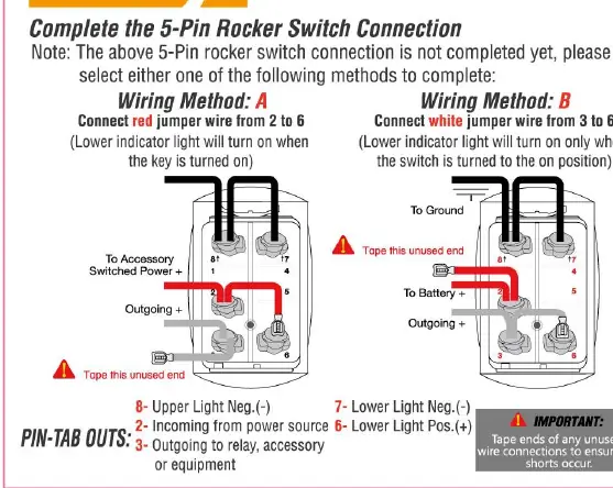
- Method A: Connect the red jumper wire from pin 2 to pin 6. The lower indicator light will illuminate when the ignition key is turned on.
- Method B: Connect the white jumper wire from pin 3 to pin 6. The lower indicator light will illuminate only when the switch is toggled to the ON position.
Always ensure that any unused wire connections are properly taped to prevent accidental shorts.
Related manuals
Related manuals from the same brand or category.
Industrial / Electrical