Power / Power Management Systems
User Manual for Projecta IntelliJay 12V Power Management System
Quick guide for the Projecta IntelliJay 12V Power Management System. Includes installation, wiring, configuration, maintenance, and troubleshooting steps for PM200-BTJ and PM235J-NODE models.
Table of contents
Manual images
Click an image to enlargeQuick guide from the manual
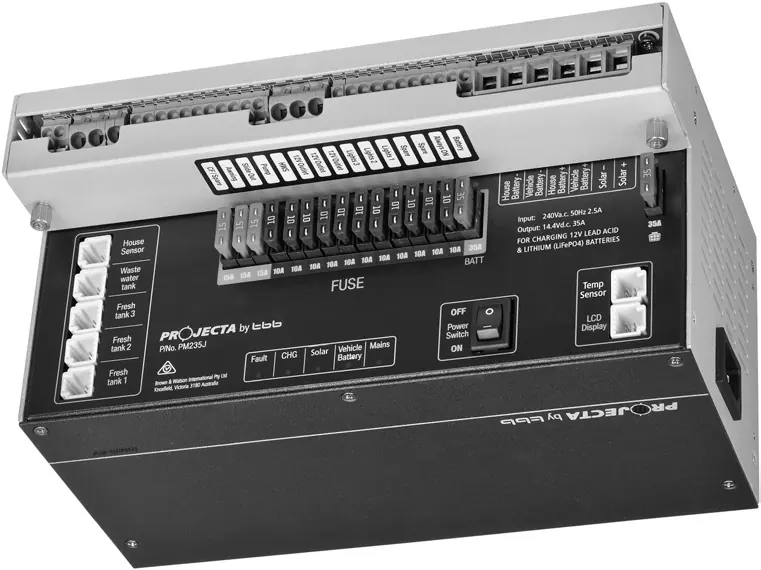
The Projecta IntelliJay 12V Power Management System is designed for caravans and motor homes. It features a central transformer unit (PM235J) that manages battery charging, power supply, solar input, and fused distribution. The system is available in two versions: the PM200-BTJ, which includes an LCD monitor, and the PM235J-NODE, which uses a Bluetooth node for app-based control.
Installation
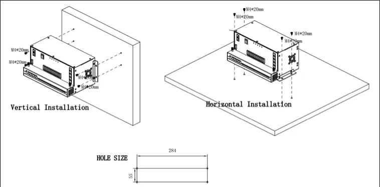
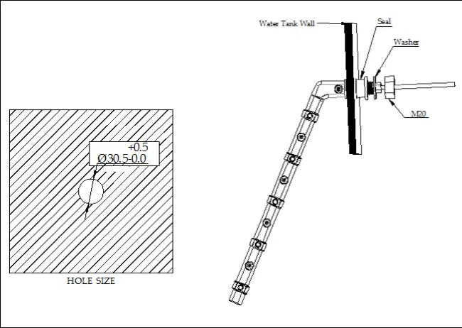
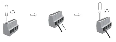
The PM235J transformer unit can be installed on a horizontal surface or vertically on a wall. Ensure a recommended clearance of 5cm on each side for ventilation. The system uses spring and screw terminals for wiring. When running cables through panels or walls, use cable glands to protect against sharp edges.
Operation
Configuration of battery type and capacity can be performed via the LCD monitor or the smart device app. The system supports AGM, GEL, LFP (LiFePO4), and WET battery types. The LCD monitor allows for system monitoring, pump control, and power isolation. The Bluetooth app provides remote monitoring of battery parameters, water tank levels, and load status.
Maintenance
To ensure accurate state of charge (SOC) monitoring, ensure the battery capacity is set correctly. Fully charge the battery via AC mains at least once every 3 months. Ensure the Power Switch is ON when charging via AC mains and maintain 10cm of space around the unit for ventilation.
Troubleshooting
The system provides diagnostic feedback via LED indicators on the transformer unit and error codes on the LCD monitor. Common issues include AC input abnormalities, solar voltage errors, and fuse failures. If a fault occurs, check the LED status or the error code list provided in the manual.
Specifications
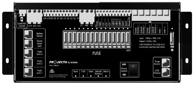
The system operates on a 240V AC input and provides a 12V DC output. It features a 35A battery charger, 30A PWM solar controller, and 14 fused outputs. The unit is rated IP20 and is designed for temperatures between -40°C and +65°C.
Practical help
Common problems
AC input abnormal (Mains LED flashing)
Check the AC mains connection.
Solar input voltage error (Solar LED flashing)
Ensure solar voltage is not exceeding 25Vdc.
Fuse blown (Fuse LED solid red)
Check the load and replace the fuse.
Short circuit (Fault LED ON)
Inspect wiring for short circuits.
Before use
- Ensure battery type and capacity are set correctly in the LCD or app.
- Verify all wiring connections match the system schematic.
- Ensure 10cm clearance on both sides of the PM235J unit for ventilation.
- Check that the battery is fully charged via AC mains before first use.
Specs in practice
- Max charging current
- 30A
- Nominal input voltage
- 240V AC
- Battery types supported
- AGM, GEL, LFP (LiFePO4), WET
- Protection category
- IP20
Images and diagrams
- Figure 8 shows the front panel layout with numbered terminals.
- Figure 17 provides the system wiring schematic.
Model compatibility
- Compatible with Lead Acid and LiFePO4 batteries.
- PM200-BTJ includes LCD monitor; PM235J-NODE uses Bluetooth node.

Manual page author
Michael Turner
Technical manual editor
Reviews PDF manuals for structure, safety notes, and practical product details so readers can find the right information quickly.