Electronics / Remote Controls
Enerdrive Wanderer Power System Installation Guide
Installation guide for the Enerdrive Wanderer Power System. Includes mounting instructions, wiring diagrams for DC and AC connections, solar input setup, battery connection procedures, and technical specifications.
Table of contents
Manual images
Click an image to enlargeQuick guide from the manual
The Enerdrive Wanderer is an all-in-one power system designed for charging, power supply, and monitoring. This guide covers the installation of the pre-assembled unit. For specific details on individual components like the DC2DC40+ charger, ePRO Inverter/Charger, or Simarine Pico Monitor, refer to their respective manuals.
Mounting
Choose a location that keeps the battery as close as possible to the system; a distance of less than 1.5m is ideal. If the distance exceeds 1.5m, you must use a larger diameter cable than the supplied 50mm2. Ensure the mounting area is free from moisture and excessive dust. Fasten the unit through the black plastic backing panel to a rigid structure in your vehicle capable of supporting the system's weight. Ensure no wiring is in the path of fasteners during installation.
Connecting Loads (Appliances)
You can connect lights, pumps, and other accessories using the four switches or directly to the circuit breaker.
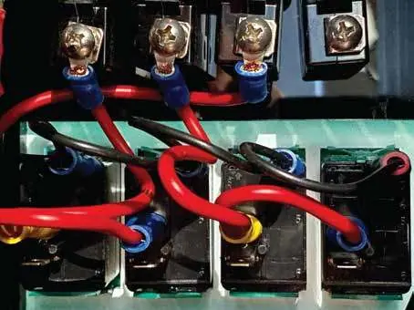
- Using Switches: Connect the positive wire to one of the four switches using insulated female spade crimps. The supply connects to the top terminal, and the load connects to the bottom terminal.
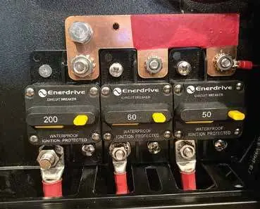
- Using Circuit Breakers: Connect directly to the appropriately labeled circuit breaker using 4mm ring terminals.
Note: Each switch is rated at 20A. Do not exceed this rating; use a relay for larger loads. Ensure cables are sized to handle the circuit breaker rating.
Negative Bus Bar Connections
Connect the negative wire from your accessories directly to the negative bus bar using 4mm ring terminals. For load circuits exceeding 30 amps, connect the negative wire directly to the Main negative Bar. Do not connect negative wires directly to the battery or the battery side of the shunt, as this will cause incorrect readings on the Simarine system.

Solar Connection
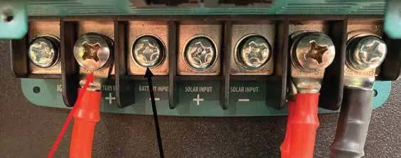
The system features an inbuilt MPPT regulator. Connect fixed or portable solar panels (via Anderson plug) directly to the DC2DC+ unit. Use a minimum 4mm2 cable with 6mm ring terminals. Ensure solar panels are disconnected or covered during the connection process.
Connecting to Main (Start) Battery
Connect the Battery Input terminals of the DC2DC+ to your vehicle's main/start battery. A 70A midi fuse must be installed as close as possible to the main/start battery. Refer to the cable sizing chart in the manual for distances between 2m and 10m.
Connection to Auxiliary Battery
Connect the auxiliary battery negative cable (minimum 50mm2/0AWG) to the Simarine shunt stud using a 10mm ring terminal. Connect the auxiliary battery positive cable to the back of the Inverter circuit breaker on the same side as the copper bus bar using an 8mm ring terminal.
Temperature Sensor
The supplied temperature sensor plugs into the Simarine SC301 shunt. It can be placed in locations such as a canopy, fridge, or freezer. Do not cut or extend this cable.
Inverter Input and Output AC Wiring
AC wiring must be performed by a licensed electrician in accordance with local requirements.
Specifications
- DC Charger: Output 40-50A; Solar Input 14.5-45VOC.
- Inverter/Charger: Output 60A; AC Output 230V 50Hz; Power 1300W continuous (1600W for 10 minutes).
- General: Dimensions 760L x 155W x 510H mm; Weight 21kg.
Manufacturer information
Enerdrive
Practical help
Common problems
Incorrect Simarine system readings
Ensure no negative connections are made directly to the battery or on the battery side of the shunt.
Voltage drop or power loss
If the battery is further than 1.5m from the system, use a larger diameter cable than the supplied 50mm2.
Switch failure or overload
Ensure accessory current ratings do not exceed 20A per switch. Use a relay for larger loads.
Before use
- Ensure the mounting structure is rigid and can support 21kg.
- Verify that no wiring is in the path of fasteners before mounting.
- Ensure solar panels are covered or disconnected during installation.
- Install a 70A midi fuse near the main/start battery.
- Verify cable sizing matches the distance and current requirements.
Specs in practice
- AC Output Power
- 1300W continuous, with a 1600W capacity for up to 10 minutes.
- Solar Input Voltage
- Accepts 14.5-45VOC.
- DC Charger Output
- Maximum 40-50A.
Images and diagrams
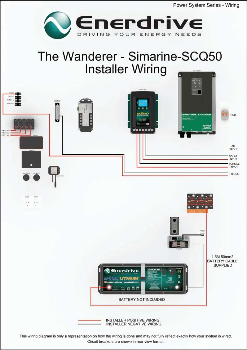
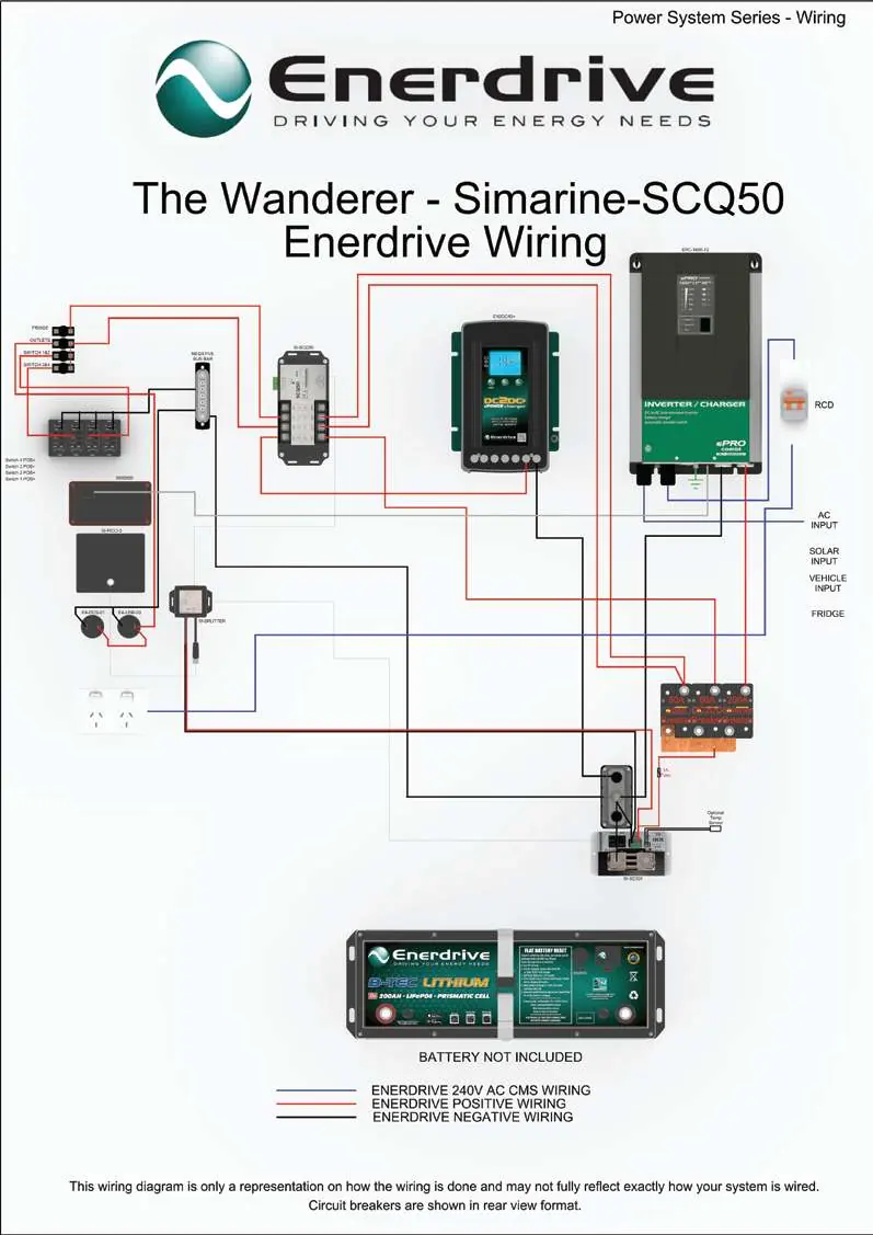
- Wiring diagrams are provided for both Installer and Enerdrive configurations, illustrating the connections between the DC2DC charger, Inverter/Charger, and battery system.
Model compatibility
- Compatible with fixed or portable solar panels via Anderson plug.
- Requires connection to vehicle main/start battery for DC2DC charging.
- AC wiring must be performed by a licensed electrician.

Manual page author
David Miller
Documentation analyst
Organizes user manual content into clear summaries, with attention to model details, product context, and everyday usability.