Lighting / LED Lamps
RAB WPLED Field-Adjustable LED Lighting Installation Guide
Comprehensive installation and configuration guide for RAB WPLED LED fixtures. Includes step-by-step mounting instructions, wiring diagrams for standard and battery backup models, field adjustment settings for CCT and power, and...
Table of contents
Manual images
Click an image to enlargeImportant Information
The RAB WPLED fixture is a field-adjustable LED lighting unit designed for wet locations. Before installation, ensure the power is OFF. The fixture must be installed in accordance with the National Electrical Code and local codes by a qualified person. For proper weatherproof function, ensure all gaskets are seated properly, screws are tightened firmly, and silicone sealant is applied around the junction box and unused conduit entries.
Installation
The fixture supports multiple mounting configurations:
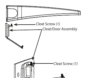
- Wall Mount: Loosen door screws, separate the cleat/door assembly, secure the assembly to the mounting surface, slide the fixture on, wire according to diagrams, and close the door.
- Surface Mount for Recessed Box: Attach the supplied crossbar to the junction box, secure the cleat/door assembly to the wall plate, attach the wall plate to the crossbar, and proceed with wiring.
- ARM24 (Uplight Mount): Requires specific accessories. Secure the cleat assembly to the threaded rod or mounting surface, slide the fixture on, and secure.
Field Adjustments
The fixture allows for field adjustments of Color Temperature (CCT), Power (Wattage), and Photocell operation:
- Locate the selector switches inside the housing.
- CCT Selection: Choose between 3000K, 4000K, or 5000K. 4000K is recommended for maximum light output.
- Power Selection: Adjust wattage based on the specific model (WPLEDS or WPLEDM).
- Photocell: Toggle the switch to ON or OFF. If enabled, note that it may take up to 60 seconds for the light to turn off in daylight.
Wiring
The fixture supports universal voltage (120V-277V). Follow the specific wiring diagram provided in the manual for your configuration:
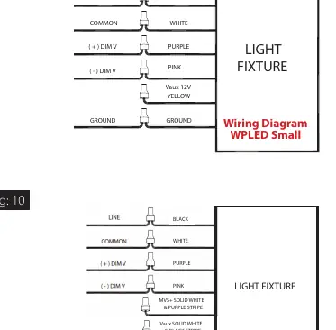
- 0-10V Dimmable Wiring: Connect line, common, ground, and dimming leads (purple/pink) as specified. Do not connect dimming leads to line voltage.
- LCBS/MVS Wiring: Follow the specific diagram for medium-sized models equipped with these features.
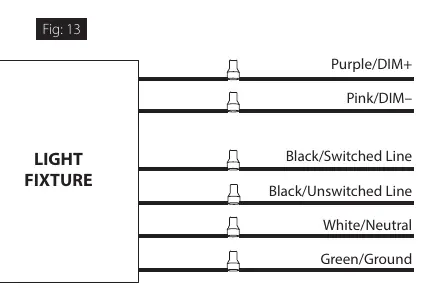
- Battery Backup Models: Requires an unswitched AC source. Connect unswitched hot, switched hot (if applicable), and dimming leads. Ensure the battery is connected and charged for at least 24 hours for full functionality.
Maintenance and Troubleshooting
Routine maintenance is minimal but recommended:
- Cleaning: Clean the lens with a non-abrasive glass cleaning solution. Do not open the fixture to clean the LED or touch the LED directly.
- Troubleshooting: If the fixture fails to operate, check line voltage, ensure proper grounding, and verify photocell functionality. For battery backup models, ensure the battery is connected if the charging indicator light does not illuminate.
- Battery Testing: Perform a 30-second test every 30 days and a 90-minute discharge test annually.
Practical help
Common problems
Light does not turn off during the day
If the Photocell is set to 'ON', it may take up to 60 seconds for the light to turn off.
Charging indicator light does not illuminate (Battery Backup models)
Check if the battery is connected properly inside the fixture.
Fixture not working
Verify that the line voltage is correct, the fixture is properly grounded, and all wiring connections match the provided diagrams.
Before use
- Ensure power is OFF before installation or maintenance.
- Verify the mounting surface can support the weight of the fixture.
- Ensure all gaskets are seated properly to maintain weatherproof seal.
- Check that the branch circuit wiring is available (especially for battery backup models).
- Verify that the chosen mounting accessories are compatible with the fixture size.
Specs in practice
- 0-10V Dimming
- Standard dimming control method; requires specific wiring of purple (V+) and pink (V-) leads.
Images and diagrams
- Fig 1 & 2: Illustrates the wall and surface mounting procedures, including screw locations.
- Fig 7 & 8: Shows the location of internal selector switches for CCT, Power, and Photocell.
- Fig 9, 10 & 11: Wiring diagrams for standard and LCBS/MVS configurations.
- Fig 13: Wiring diagram specifically for battery backup models.
Model compatibility
- Suitable for wet locations as a downlight.
- Uplight installation requires specific accessories (ARM24S, ARM24M, etc.).
- Battery backup models require an unswitched AC source.

Manual page author
Emily Carter
User documentation editor
Prepares concise manual descriptions and highlights the most useful setup, operation, and maintenance information for readers.