Lighting / LED Modules
RZB LINEDO LED Complete Module Installation Manual
Comprehensive installation and wiring guide for the RZB LINEDO LED complete module. Includes mounting instructions, electrical connection diagrams, safety guidelines, and technical specifications.
Table of contents
Manual images
Click an image to enlargeImportant Information
The RZB LINEDO LED complete module is a professional lighting fixture designed for ceiling or pendant mounting. Installation must be performed by qualified personnel in accordance with local safety and accident prevention regulations. The system supports various feed-in configurations and connector types (L, X, T) to suit different installation layouts.
Safety Information
- Electrical Connection: Must comply with all applicable national and international standards.
- Ambient Temperature: Operating range is -25 °C to +40 °C. Exceeding this range reduces the luminaire's lifespan and may cause premature failure.
- Modifications: Any modification, reworking, or re-labeling of the product or packaging is strictly prohibited and voids warranty/liability.
- Damaged Components: Do not operate damaged luminaires. Replace any cracked protective shields immediately according to DIN EN 60598.
Technical Specifications
- Voltage: 220 - 240 V, 0/50/60 Hz
- Protection Rating: IP 54 (dust and splash-proof), IK03
- Light Source: Energy efficiency class C (according to EU 2019/2015)
- Weight: 9.6 kg
- Dimensions: L 4547 mm, B 58 mm, H 76 mm
Installation and Mounting
The LINEDO system supports both pendant and ceiling mounting. Ensure the ceiling and fastening elements have sufficient load-bearing capacity before installation.
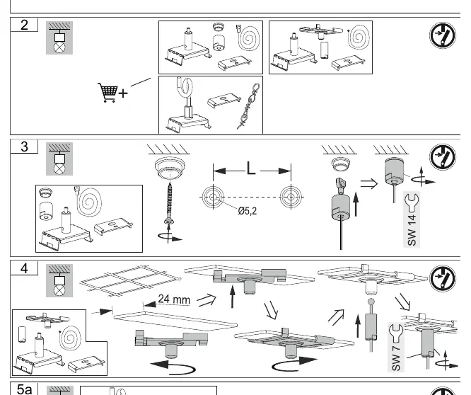
Mounting Steps
- Prepare the mounting surface and ensure stability.
- Select the appropriate mounting method (pendant or ceiling) based on the site requirements.
- Use the provided mounting hardware to secure the fixture.
- For pendant mounting, ensure the suspension points are correctly aligned and secured.
Wiring and Electrical Connection
The system allows for flexible wiring configurations, including feed-in from the middle, beginning, or side. The factory setting is L1. Users can adjust the phase connection (L1, L2, L3) using the internal connector block.
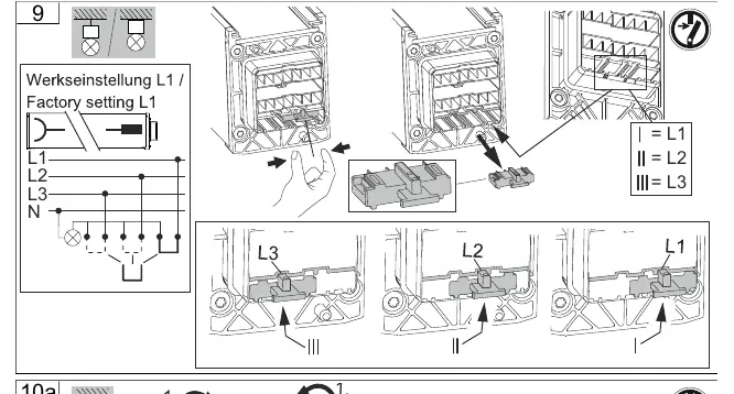
- ESD Prevention: Do not route feed-through wiring directly along the luminaire wiring to avoid electromagnetic interference.
- Dimmable Luminaires: Connect control inputs using standard cables suitable for the power supply voltage.
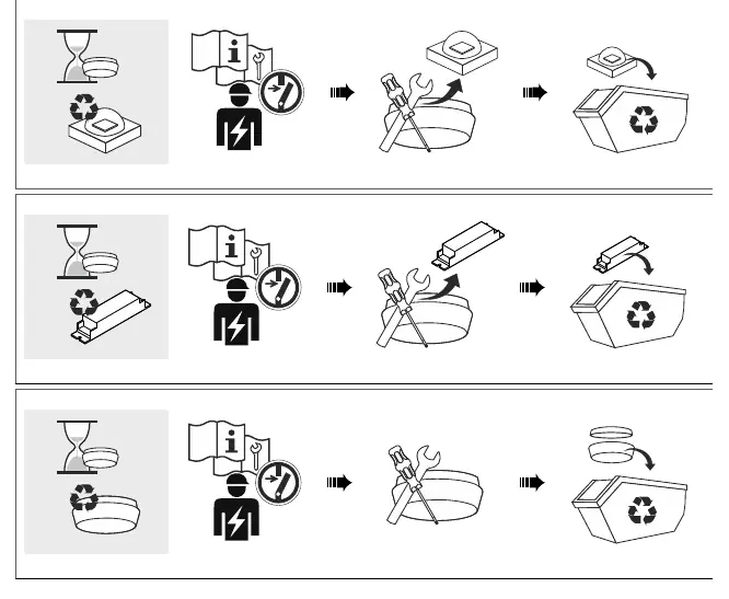
Maintenance and Disposal
The light source contained in this luminaire must only be replaced by the manufacturer, a service agent, or a similarly qualified person. Do not attempt to replace the light source yourself. At the end of its service life, the product and its components should be disposed of according to local environmental regulations.
Practical help
Common problems
Luminaire not functioning
Verify the electrical connection and ensure the phase (L1, L2, or L3) is correctly configured in the connector block.
Premature failure
Check if the ambient temperature exceeds the allowed range of -25 °C to +40 °C.
Cracked protective shield
The shield must be replaced immediately to maintain safety standards (DIN EN 60598).
Before use
- Ensure the ceiling and mounting surface can support the weight of the fixture (9.6 kg).
- Verify the supply voltage is within the 220-240V range.
- Check that the installation environment is free from conductive dust if IP54 protection is required.
- Confirm all electrical connections are made by a qualified professional.
- Ensure the correct wiring configuration (L1, L2, or L3) is selected for your power circuit.
Specs in practice
- Ambient Temperature
- The operating temperature range (-25 °C to +40 °C) required to maintain product lifespan.
Images and diagrams
- Wiring diagrams illustrate feed-in options (middle, beginning, side) and connector types (L, X, T).
- Mounting diagrams show the step-by-step process for pendant and ceiling installation.
Model compatibility
- Light source replacement must be performed by the manufacturer or a qualified service technician.
- Modifications to the product or packaging are not permitted.

Manual page author
Emily Carter
User documentation editor
Prepares concise manual descriptions and highlights the most useful setup, operation, and maintenance information for readers.