Industrial / Stepper Motors
User Manual for Safran FemtoStepper 100FS
Quick guide for the Safran FemtoStepper 100FS. Learn about installation, RS232 control commands, system connections, and status indicators.
Table of contents
Manual images
Click an image to enlargeQuick guide from the manual
The Safran FemtoStepper 100FS is a high-performance phase stepper designed to provide a highly stable 10MHz signal, adjustable in phase and frequency with extremely high resolution. It also provides a one pulse per second (1PPS) output generated from the 10MHz signal. The device is controlled remotely via an RS-232 serial link.
Installation and connections
Before installing, ensure you use proper ESD precautions. Unpack the unit and inspect for physical damage. The unit supply includes the FemtoStepper rack, a SUB-D 9-pin cable, a Euro power cable, rack mount brackets, and a connector for the backup power supply.

Interface connections:
- J1: 230VAC primary power input.
- J2: +24VDC backup power input.
- J3: COM Interface (Sub-D-9P-FEM).
- J4: Ground connection (Screw M4).
- J5: 10 MHz reference signal input (SMA).
- J6: PPS reference signal input (SMA).
- J7-J10: 4x PPS output (SMA).
- J11-J14: 4x 10MHz output (SMA).
Connect the 10MHz input reference to J5. If PPS functionality is required, connect the PPSref signal to J6. Connect the COM cable to J3 and your computer. Connect power cables to J1 and J2, and optionally connect the device to ground at J4.
System operation
Switch on the unit using the S1 switch. The front panel indicators provide status updates:
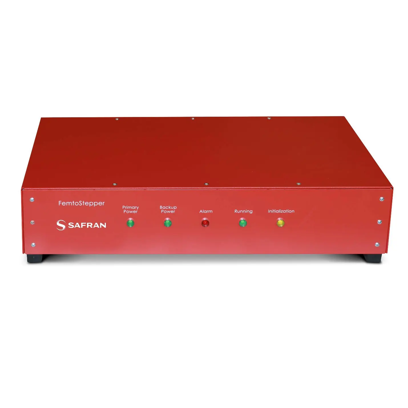
- L1 (Green): Primary power active.
- L2 (Green): Backup power active.
- L3 (Red): Alarm indicator. This will be red during the warm-up period (approx. 15 minutes). If it remains red, check the input reference at J5.
- L4 (Green): Running indicator. Becomes green when ready. Blinks when a frequency offset is applied.
- L5 (Yellow): Initialization indicator. Switches off after the initial 5-second sequence.
It is recommended to warm up the unit for several hours before use and keep it powered on to reduce warm-up time.
RS232 control
The device is controlled remotely via RS-232. The communication protocol is: 9600 bits/s, 8 data bits, no parity, 1 stop bit, and no handshake.
Key commands include:
- ID: Identification.
- SN: Serial Number.
- ST: Status.
- PS: Single Phase Step.
- PH: Actual Phase Offset.
- FA: Frequency Offset.
- FR: Actual Frequency Offset.
- FD: Frequency Drift.
- AL: Align PPSOUT to PPSREF.
- DE: Set PPSOUT delay.
- BT: Send Information Every Second.
Technical support
For technical support, visit the Safran navigation timing support hub at https://safran-navigation-timing.com/support-hub/ to submit a support request. For additional documentation, visit the product page at https://safran-navigation-timing.com/product/femtostepper/
Official resources from the manual
Practical help
Common problems
Alarm indicator (L3) stays red
The unit is warming up (approx. 15 mins). If it remains red after this time, check if an input reference signal is connected to J5.
PPSOUT alignment fails
Ensure the PPSREF signal is connected to J6 and the AL1 command has been sent.
Communication failure
Verify RS232 settings: 9600 bits/s, 8 data bits, no parity, 1 stop bit, no handshake.
Before use
- Use proper ESD precautions.
- Inspect the unit for physical damage upon unpacking.
- Connect 10MHz input reference to J5.
- Connect primary power (230VAC) to J1.
- Connect backup power (+24VDC) to J2 if required.
- Warm up the unit for several hours before starting applications.
Specs in practice
- 10MHz Output
- Highly stable signal adjustable in phase and frequency.
- RS232 Protocol
- 9600 bits/s, 8 data bits, no parity, 1 stop bit, no handshake.
- Heterodyne Gain
- G = 10^6.
Images and diagrams
- Figure 5: Interfaces shows the location of power inputs, COM port, and signal SMA connectors on the back panel.
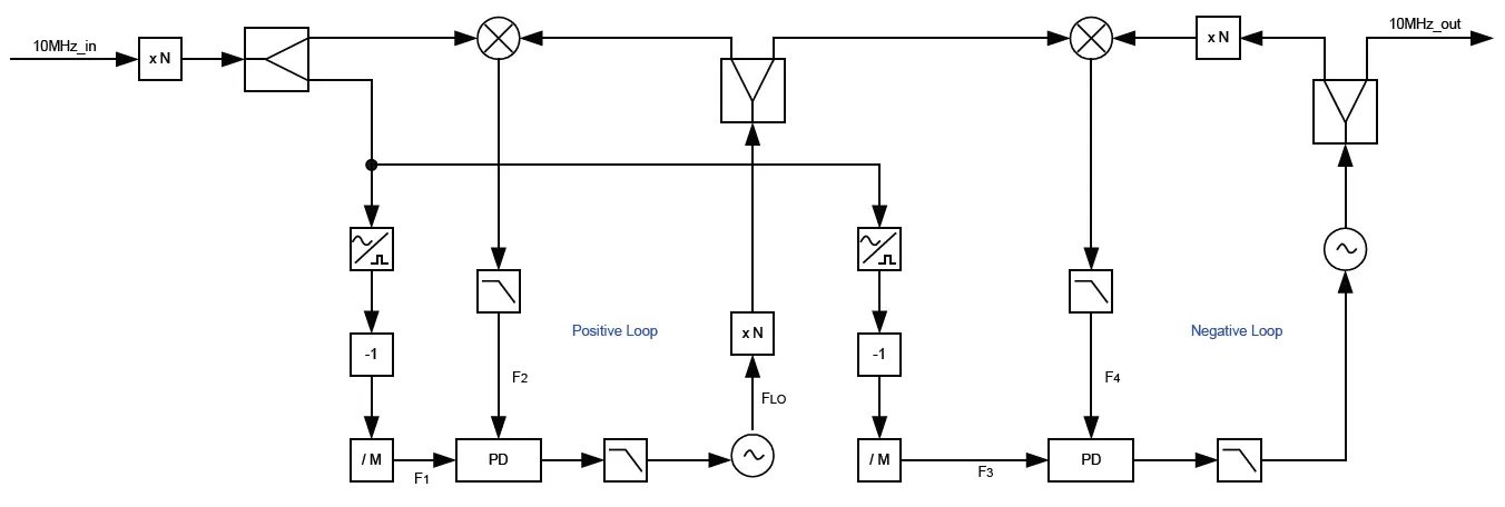
- Figure 3: Microprocessor illustrates the internal control loop for PPS alignment and phase/frequency control.
Model compatibility
- Requires external 10MHz reference input.
- Requires RS232 serial connection for remote control.

Manual page author
David Miller
Documentation analyst
Organizes user manual content into clear summaries, with attention to model details, product context, and everyday usability.