Tools / Laser Engraving Accessories
Installation Guide for Genmitsu Nema23 112mm Stepper Motor Kit
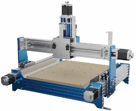
A comprehensive installation guide for the Genmitsu Nema23 112mm Stepper Motor Kit designed for the PROVerXL 4030. This manual provides step-by-step instructions for removing original motors, installing the new kit, wiring the control box...
Table of contents
Manual images
Click an image to enlargeQuick guide from the manual
This document provides instructions for installing the Upgraded Nema23 112mm Stepper Motor Kit on the PROVerXL 4030. For technical support, please email [email protected] or join the SainSmart Genmitsu CNC Users Group on Facebook.
Package List
- 1: 542 Control Box
- 2: (4) 112 Stepper Motor
- 3: (2) M4*12 Socket Head Cap Screws
- 4: (2) M5*50 Socket Head Cap Screws
- 5: (2) M5*55 Socket Head Cap Screws
- 6: Hex Key Set (2, 2.5, 3, 4)
Installation Guide
The installation process involves removing the original motors and replacing them with the new 112 stepper motors. If screws become slippery during installation, use the spare screws provided in the kit.


Removing Original Motors (Steps 1-5)
- Disconnect the motor wiring.
- Loosen the top bolts and the socket head cap screw on the motor-facing side of the axis coupling.
- Remove the 4 motor fixing screws.
- Remove the original motor.
- Repeat these steps for the X, Z, Y1, and Y2 axes.
Installing New Motors (Steps 6-10)
- Mount the 112 stepper motor onto the motor mount.
- Secure the motor using the disassembled fixing screws.
- Tighten the socket head cap screws and the top bolt on the motor side of the coupling.
- Connect the motor cable.
- Repeat for all axes.
Control Box Wiring Diagram
Connect the cables to the control box ports as follows:
- Motors: X-Motor, Y1-Motor, Y2-Motor, Z-Motor
- Limits: X-Limit, Y-Limit, Z-Limit
- Other: Probe
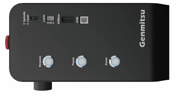
The control box also features switches for Spindle/Laser, Laser mode, Offline control, and a USB port.
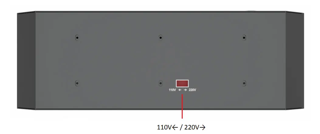
Adjust Voltage of Control Box
Before operation, ensure the voltage setting on the bottom of the control box matches your country's requirements. Use the switch to select between 110V and 220V.
Practical help
Common problems
Screws are slippery or stripped during installation
Use the spare screws included in the kit to replace them.
Incorrect voltage setting
Adjust the voltage switch on the bottom of the control box to the option that suits your country's voltage requirements (110V or 220V).
Before use
- Verify all 4 motors are included in the package.
- Ensure you have the correct hex keys (2, 2.5, 3, 4) ready.
- Check the voltage setting on the bottom of the control box before plugging it in.
- Disconnect power before performing any wiring or motor installation.
Images and diagrams
- The control box wiring diagram identifies ports for X, Y1, Y2, and Z motors, as well as limit switches and the probe.
- The control box side panel shows switches for Spindle/Laser selection, Laser mode, Offline control, and USB connectivity.
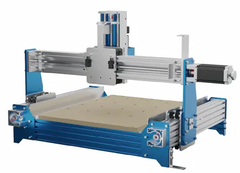
Model compatibility
- This kit is specifically designed for the PROVerXL 4030.

Manual page author
Michael Turner
Technical manual editor
Reviews PDF manuals for structure, safety notes, and practical product details so readers can find the right information quickly.