Lighting / Fixtures
Saxby Lighting 108HT Retro-Fit Anti Glare Downlight Installation Guide
A comprehensive installation and maintenance guide for the Saxby Lighting 108HT Retro-Fit Anti Glare Downlight. Includes wiring diagrams, safety warnings, bulb replacement instructions, and technical specifications.
Table of contents
Manual images
Click an image to enlargeQuick Start and Safety
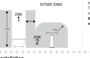
The Saxby Lighting 108HT is a Class 1 light fitting that must be earthed. It is rated IP20, meaning it has no special protection against moisture and is not suitable for use in bathroom Zones 0, 1, or 2. Installation must be performed by a competent and qualified electrician in accordance with IEE Wiring regulations and current Building Regulations.
Installation
Before starting, ensure the mains supply is switched off and cannot be restored by others. Existing fittings must be removed completely before installing the new unit.
- Ceiling Preparation: The ceiling surface must be flat and smooth. Cut a 75mm mounting hole in the ceiling, taking care not to damage pipes or cables. It is recommended to cut the hole slightly smaller and file it until the unit fits snugly.
- Ceiling Void: Ensure a minimum ceiling void depth of 150mm is available.
- Spacing: If installing multiple downlights, maintain a minimum distance of 0.5m (50cm) between units.
- Insulation: Ensure free movement of air around the fitting by removing any roof void insulation from at least 150mm around the hole. Under no circumstances must these fittings be covered with insulating matting or similar material.
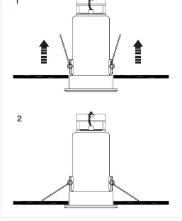
- Mounting: Push the spring clips upwards and fit the two longer arms into the ceiling hole. Push the unit up until it is firmly in position, ensuring the cable is not trapped or snagged.
Wiring
After identifying the wiring from your existing fitting, pull the wire through the hole in the ceiling. Remove the cover from the terminal block and connect the wires as follows:
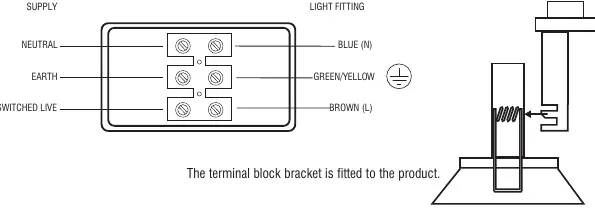
- Neutral: Blue (N)
- Earth: Green/Yellow
- Switched Live: Brown (L)
Ensure that all connections are tight, no loose strands are left out of the connection block, and the input cable is fitted under the clamp.
Bulb Replacement
Always switch off the mains supply and allow the bulb to cool before handling. Dispose of used bulbs carefully. To replace the bulb, rotate it anticlockwise to release it from the holder, insert the new bulb, and reverse the process. Do not exceed the maximum wattage stated (50W) or use a different shape bulb than indicated.
Technical Specifications
- Voltage: 240V 50Hz a.c.
- Lamp: 1 x Max. 50W GU10 Mains Halogen
- IP Rating: 20
- Class: Class 1 (Must be earthed)
Practical help
Common problems
Light does not turn on
Check that the fuse or circuit breaker is replaced and switched on. Verify that all wiring connections are tight and correctly identified.
Bulb is difficult to remove
Ensure the power is off and the bulb has cooled. Rotate the bulb anticlockwise to release it from the holder.
Cable snagging during installation
Adjust the cable position before pushing the unit fully into the ceiling hole to ensure it is not trapped.
Before use
- Ensure the ceiling surface is flat and smooth.
- Verify that the mains supply is switched off.
- Confirm a 75mm mounting hole is cut.
- Ensure a minimum ceiling void depth of 150mm.
- Check that insulation is removed from at least 150mm around the hole.
- Verify that the wiring matches the terminal block labels (Neutral, Earth, Switched Live).
Specs in practice
- 0.5m Spacing
- Minimum distance required between multiple downlight units.
Images and diagrams
- The wiring diagram illustrates the connection of Neutral (Blue), Earth (Green/Yellow), and Switched Live (Brown) to the terminal block.
- The installation diagram shows the spring clip mechanism used to secure the unit into the ceiling hole.
Model compatibility
- Suitable for dimming if used in conjunction with a dimmable lamp (verify with lamp manufacturer).
- LED bulbs are suitable for use in this product.

Manual page author
Michael Turner
Technical manual editor
Reviews PDF manuals for structure, safety notes, and practical product details so readers can find the right information quickly.