Tools / Generators
Solplanet ASW 05-12kH-T2/T3 Three Phase Hybrid Inverter User Manual
Quick guide for the Solplanet ASW 05-12kH-T2/T3 series hybrid inverters, covering installation, electrical connections, commissioning, and energy management settings.
Table of contents
Manual images
Jump to the sectionQuick guide from the manual
This document provides essential instructions for the installation, commissioning, and operation of Solplanet ASW 05-12kH-T2 and T3 series three-phase hybrid inverters. These inverters are designed for indoor and outdoor use, converting solar energy to AC and managing battery storage. Installation must be performed by qualified personnel.
Device description
The inverter features mounting ears, fixed points, handles, and distinct wiring areas for DC, communication, and AC connections. It includes an integrated LED display for status monitoring (SOLAR, BAT, ERR, EPS, GRID).
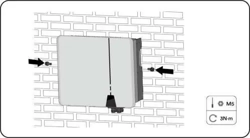
Mounting
The inverter must be mounted on a solid surface (concrete or masonry) capable of supporting four times its weight. Ensure adequate clearance (at least 500mm) around the unit for ventilation. Avoid direct sunlight and ensure the unit is installed vertically.

Electrical connection
Connections include PV strings, battery, grid, and EPS load. Ensure correct polarity for all DC connections. The system supports various grid types (TN-S, TN-C, TN-C-S, TT). Use the provided connectors and follow the specified torque requirements for all terminals.
Commissioning
Before commissioning, ensure all connections are secure and the DC switch is off. Use the Solplanet App to configure grid codes, battery models, and energy management modes. Once configured, turn on the AC and EPS breakers to start operation.
Energy Management
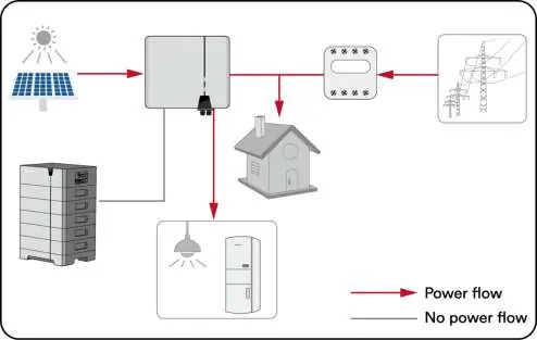
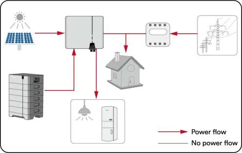
The inverter offers four modes: Self-Consumption, Reserve, Off-grid, and Custom. These can be configured via the Solplanet App to optimize energy usage based on PV generation and battery status.
Troubleshooting
The inverter displays error codes on the screen and in the app. Common issues include grid faults, isolation faults, or communication errors. Always disconnect the inverter from all power sources before performing any maintenance or troubleshooting.
Maintenance
Annual cleaning of the DC switch contacts and ensuring air inlets/outlets are free of obstructions is required for optimal performance.
Manufacturer information
Solplanet
Practical help
Common problems
Permanent Fault (Error 1-6, 8, 9)
Disconnect from battery, grid, and PV array. Wait 3 minutes and reconnect. Contact service if the fault persists.
Grid voltage fault (Error 34)
Check grid voltage at the connection point. If outside permissible range, contact the grid operator.
Isolation fault (Error 38)
Check PV array insulation to ground (must be > 1 Mohm). Inspect PV cables and modules.
Meter or CT loss (Error W192)
If CT is enabled, check phase sequence and connections. If meter is enabled, check communication connection.
Before use
- Ensure the inverter is correctly mounted with the wall bracket.
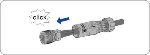
- Verify that the communication cable and AC connector are correctly wired and tightened.
- Confirm the inverter's exposed metal surface is grounded.
- Ensure DC voltage of strings does not exceed inverter limits.
- Verify correct polarity of DC connections.
- Ensure the grid voltage at the connection point complies with inverter specifications.
Specs in practice
- Max. input voltage
- 1100 V; must not be exceeded by PV string open-circuit voltage.
- Operating temperature
- -25°C to +60°C; optimal operation recommended below 40°C.
- Protection class
- IP66; suitable for indoor and outdoor installation.
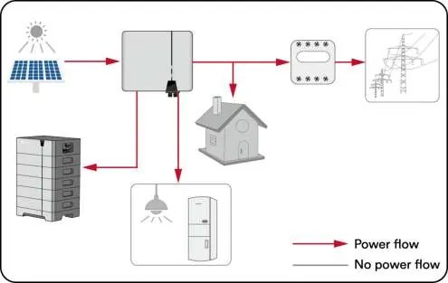
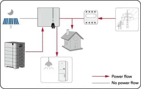
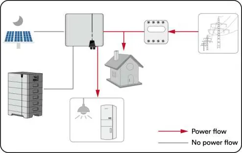
Images and diagrams
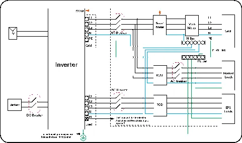
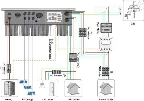
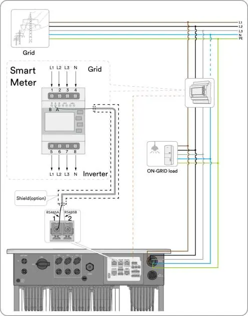
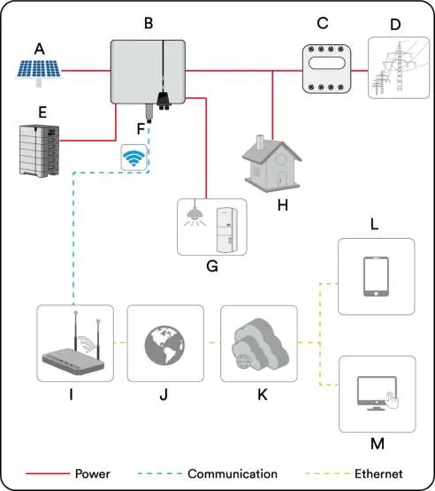
- The system diagram shows the connection of PV strings, battery, inverter, smart meter, and grid.
- For Australia/NZ, the neutral cable of the on-grid and EPS side must be connected together per AS/NZS 3000.
Model compatibility
- Only use lithium-ion batteries approved by AISWEI.
- Only Eastron and CHINT smart meters are supported.
- CTs should not be used in parallel systems.

Manual page author
David Miller
Documentation analyst
Organizes user manual content into clear summaries, with attention to model details, product context, and everyday usability.