HVAC / Air Conditioners
User Manual for Temptress 12V DC Air Conditioner Kit
Comprehensive installation and operation guide for the Temptress 12V DC Air Conditioner Kit. Includes step-by-step instructions for plumbing, wiring, refrigerant charging, and thermostat configuration for marine and RV applications.
Table of contents
Manual images
Click an image to enlargeQuick guide from the manual
This manual provides instructions for installing and operating the Temptress 12V DC Air Conditioner Kit, suitable for boats, RVs, and off-grid cabins. The system is designed to be battery-powered and requires specific plumbing and electrical connections. Key steps include preparing the air handler, installing the condenser (marine or air-cooled), connecting the refrigeration lines, wiring the compressor control board, and charging the system with R-134a refrigerant.
System Overview
The system consists of two main components connected by refrigeration tubing:
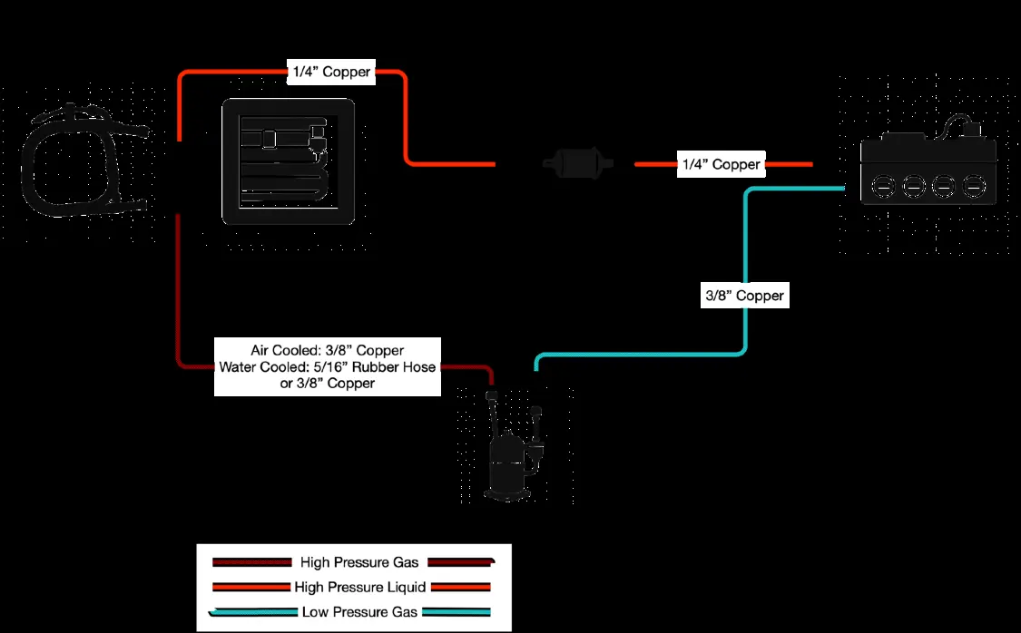
- Compressor sled: Includes the compressor, condenser, and control circuitry.
- Air handler: Contains the air blower, evaporator, expansion valve, and condensation collection assembly.
The kit includes the compressor, control board, thermal cut-off switch, potentiometer, condenser (seawater or air-cooled), filter/dryer, air handler, fan speed controller, thermostat/humidistat, 24V relay, and voltage converter (for 12V models).
Installation
The installation process varies slightly depending on whether you are using a marine (water-cooled) or RV/Tiny Home (air-cooled) setup.
Air Handler Preparation
The air handler requires an upgrade to the fan speed control system. Remove the existing temperature and speed controllers and the resistor pack. Connect the fan motor wires directly to the new speed controller.
Expansion Valve Replacement
The kit includes an upgraded expansion valve. Ensure the valve is installed vertically. Secure the temperature bulb in the exact location of the original and wrap it with the supplied insulating tape.
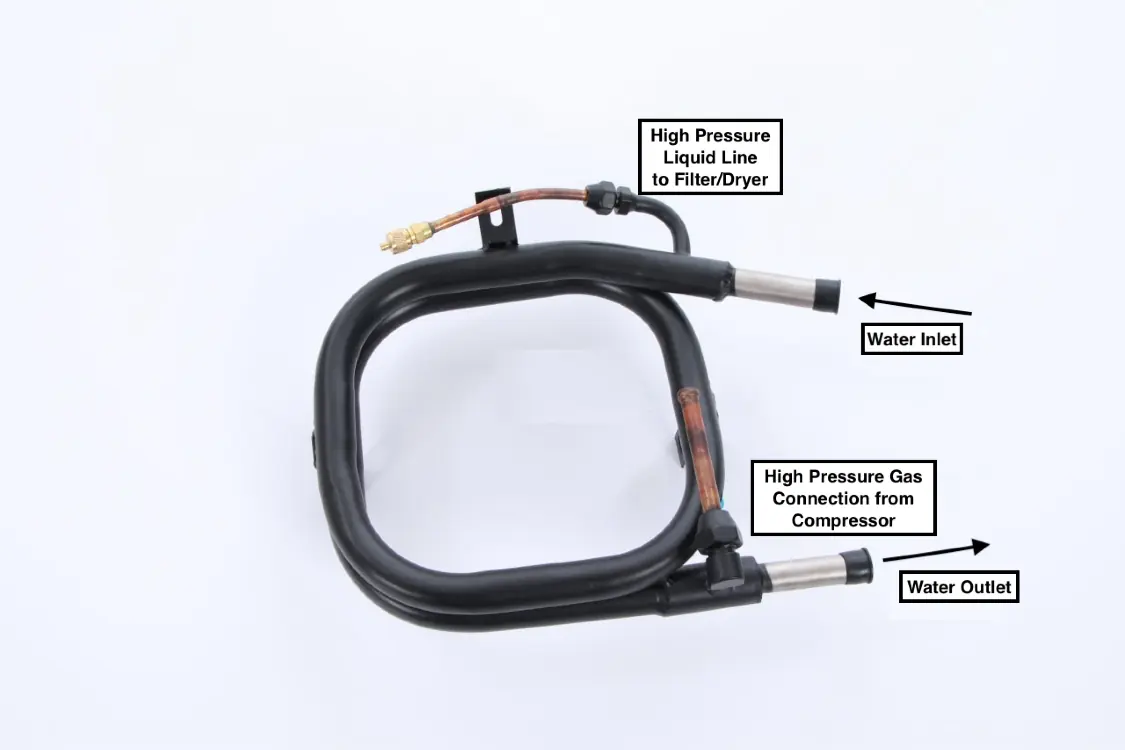
Condenser Installation
For RV/Tiny Home versions, prepare the air-cooled condenser by drilling pilot holes and installing the rubber gasket and fan adapter plate. Ensure the seal is airtight.
Plumbing
The refrigeration circuit consists of a high-pressure side and a low-pressure side.
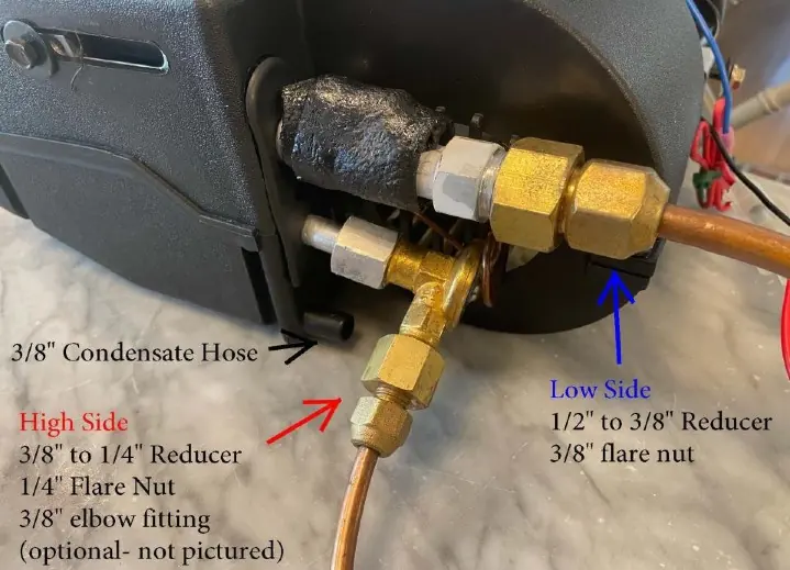
- High-pressure side: Runs from the compressor output to the condenser, through the filter/dryer, and to the expansion valve side of the air handler.
- Low-pressure side: Returns low-pressure gas from the air handler to the compressor vacuum return port.
Use opposing wrenches when tightening flare nuts to avoid damaging the fittings. Ensure all copper tubing is flared correctly.
Wiring
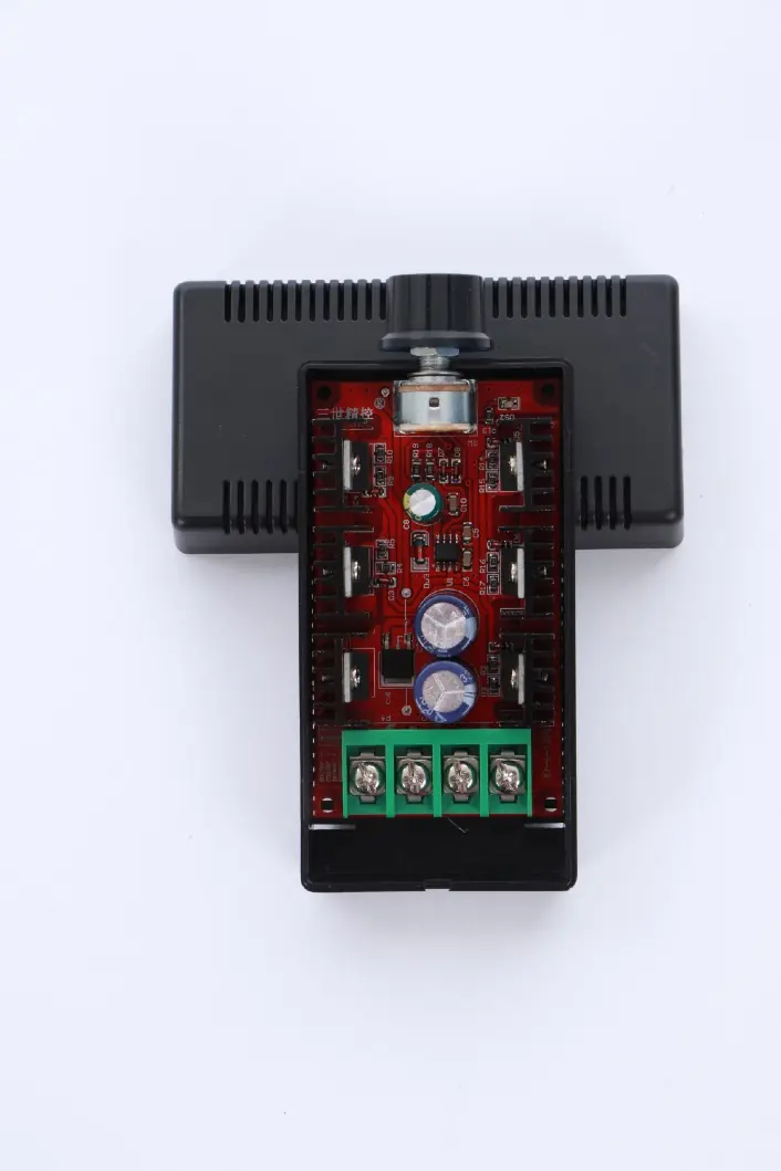
The system requires careful wiring of the compressor control board, relay, and thermostat.
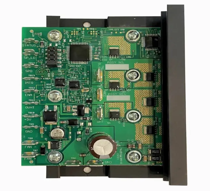
- Voltage Converter: Used for 12V applications to provide 24V power to the control board.
- Compressor Control: Connect the three-phase plug to the compressor. Match wire colors (Black, Red, White) to the pins on the control board.
- Relay: Connect the 24V relay to activate the water pump and air handler fan.
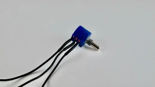
- Potentiometer: Used to adjust compressor speed. Wire to SPD, GND, and +5V terminals on the control board.
Charging
The system must be evacuated and charged with R-134a refrigerant.
- Vacuuming: Connect a vacuum pump to the high and low-pressure ports. Run until pressure is below -30 inches Hg for at least 30 minutes.
- Charging: Use the SuperCool app to guide the charging process. Monitor the high-pressure gauge and the temperature of the copper tube leaving the compressor. Aim for a subcool target of 10 degrees F.
Operation
The thermostat controls the air conditioner based on temperature and humidity settings. The top button sets the turn-on threshold, and the bottom button sets the turn-off threshold. Ensure the turn-on setting is higher than the turn-off setting for cooling mode (indicated by 'C' on the display). For dehumidification mode, the display will show 'd'.
Practical help
Common problems
Pressure rises after vacuuming
This indicates a leak or moisture in the system. Check connections for leaks or continue vacuuming to remove moisture.
Compressor overheating
Ensure the compressor is mounted with the base down in a well-ventilated area. Add a small fan if necessary.
Inefficient cooling
Ensure the air handler intake is not blocked. The system may need time to remove humidity from the air before the temperature drops significantly.
Before use
- Verify all kit components are present (Compressor, Air handler, Condenser, etc.).
- Ensure you have necessary tools: refrigeration gauges, vacuum pump, flare tool, and multimeter.
- Obtain required additional parts: copper tubing, R-134a refrigerant, fuses, and electrical wire.
- Confirm electrical wire gauges (10, 12, and 18 gauge) and thermostat wire.
- Ensure proper fuses (30A, 15A, 1A) are available for circuit protection.
Specs in practice
- Subcool target
- 10 degrees F; the target value to achieve during the charging process.
- High-pressure side
- The line handling output from the compressor to the condenser and filter/dryer.
- Low-pressure side
- The line handling return gas from the air handler to the compressor.
Images and diagrams
- Component Overview: Illustrates the refrigeration circuit connections between the condenser, filter/dryer, evaporator, and compressor.
- Compressor Control Board: Pinout diagram showing connections for the thermostat, potentiometer, and relay.
Model compatibility
- Marine applications require a seawater condenser.
- RV/Tiny Home applications require an air-cooled condenser and fan.
- The system is 12V, but a voltage converter is included for 24V components.

Manual page author
Emily Carter
User documentation editor
Prepares concise manual descriptions and highlights the most useful setup, operation, and maintenance information for readers.