Furniture / Home Furnishing
Installation and Operation Manual for The Outdoor Plus DT041723 Dial Timer
Quick guide for The Outdoor Plus DT041723 mechanical dial timer, covering installation steps, wiring diagrams, operation, and troubleshooting.
Table of contents
Manual images
Jump to the sectionQuick guide from the manual
The Outdoor Plus DT041723 is a mechanical dial timer designed to replace standard wall switches for controlling outdoor devices like lighting, irrigation, and pool pumps. It is energy-efficient and does not require electricity to function. Warning: Installation and service must be performed by qualified personnel only due to electric shock hazards.

Installation


- Turn off power at the circuit breaker.
- Remove the existing switch cover plate.
- Strip wires approximately 0.5 inches according to the gauge on the back of the timer.
- Insert wires under the terminal screw pressure plates and tighten securely using copper wire only.
- Install the timer into a 2.5-inch deep junction box, ensuring the 'TOP' mark is correctly oriented. Secure with provided screws.
- Attach the time dial plate over the threaded extension, ensuring the 'OFF' mark is at the top.
- Secure the dial plate with the provided nut (do not overtighten).
- Attach the knob to the 'D' shaped shaft, aligning the pointer with the 'OFF' mark.
- Restore power at the circuit breaker.
Operation
To set the timer, turn the knob clockwise to the desired time. The device will automatically turn off once the time elapses. If the timer is wired for reverse action, it will turn the device on at the end of the preset time.
Safety
- Do not use for precision timing applications (e.g., sun lamps, saunas).
- Do not touch with wet hands.
- Do not disassemble; there are no user-serviceable parts inside.
- Ensure power is off before maintenance.
- Do not use in areas with flammable gases or liquids.
Troubleshooting
- Timer doesn't turn ON: Check power source connections and programming.
- Timer turns ON but not OFF: Verify programming and check for damage.
- Inaccurate timing: Ensure the clock is set correctly and the power source is stable.
- Timer makes noise: Check for loose connections or potential unit failure.
Practical help
Common problems
Timer does not turn on the connected device
Verify the timer is properly connected to the power source and the device. Check that the timer is programmed correctly.
Timer turns on but fails to turn off
Check the timer settings and ensure the unit is not damaged or malfunctioning.
Timer makes unusual noises
Check all electrical connections for security. If the noise persists, the timer may need replacement.
Before use
- Ensure the junction box is at least 2.5 inches deep.
- Use only copper wire for connections.
- Verify the 'TOP' orientation on the timer before fastening.
- Ensure the 'OFF' mark is facing up when installing the dial plate.
- Confirm the knob pointer is aligned with 'OFF' before operation.
- Turn off the circuit breaker before starting installation.
Specs in practice
- Resistive Rating
- 20 Amp at 125 VAC; 10 Amp at 250/277 VAC (50/60 Hz).
- Tungsten Rating
- 7 Amp at 125 VAC.
- Motor Rating
- 1 HP at 120 VAC; 2 HP at 240 VAC (50/60 Hz).
Images and diagrams
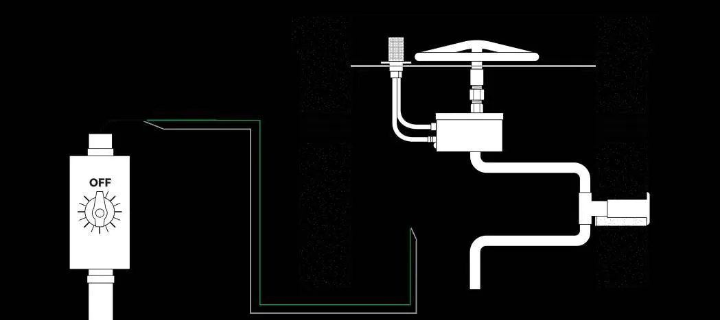
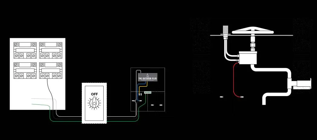
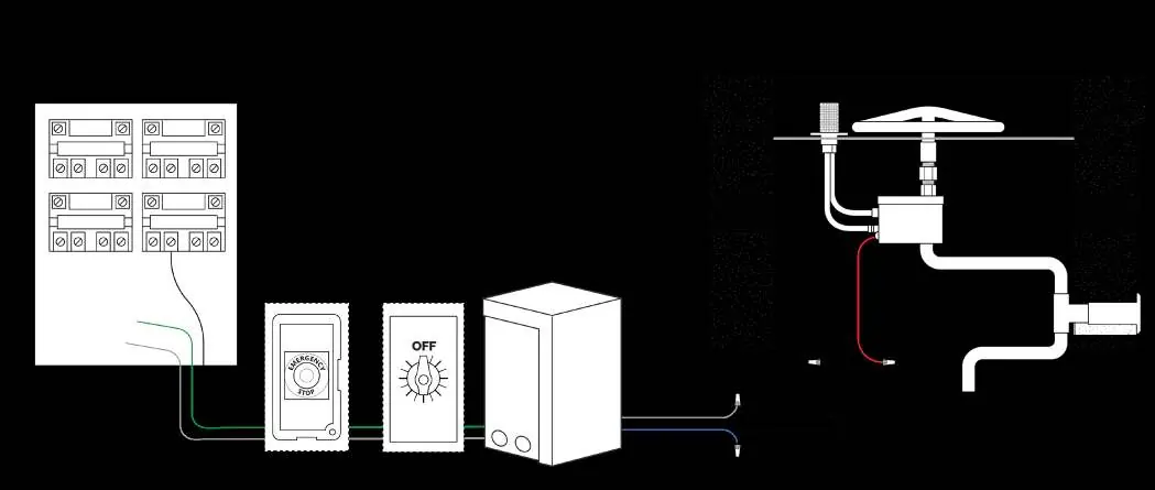
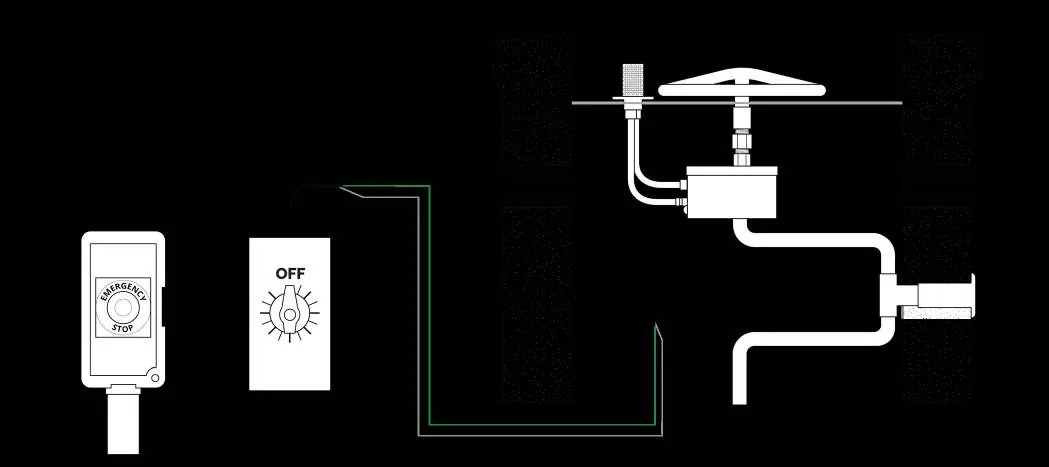
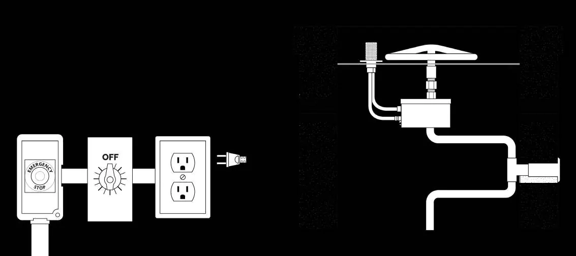
- The manual provides multiple wiring diagrams for different configurations, including setups with automated pool controllers, 12VAC control panels, and emergency stop buttons.
- Diagrams illustrate the connection path from the 110V power source through the timer to the ignition control box and gas valve components.
Model compatibility
- Designed as a replacement for standard single or multi-gang wall switches.
- Compatible with single pole, 3-way, or double pole single throw switches depending on the specific model.

Manual page author
David Miller
Documentation analyst
Organizes user manual content into clear summaries, with attention to model details, product context, and everyday usability.