Home / Electrical Timers
User Manual for The Outdoor Plus 1-Hour Gas Timer with E-Stop
Quick guide for the The Outdoor Plus 1-Hour Gas Timer with E-Stop (OPT-ESTOPTM). Includes installation instructions, operation steps, troubleshooting, and technical specifications for this mechanical gas valve.
Table of contents
Manual images
Click an image to enlargeQuick guide from the manual
The 1-Hour Gas Timer with E-Stop is a mechanical device designed to control gas flow to appliances like fire pits, grills, and gas logs. It requires no batteries or electricity. Important: Installation must be performed by a trained, experienced service technician or gas plumber. Always conduct a gas leak test after installation is complete.
Description
This device acts as an emergency shut-off, mechanical timer, and manual shut-off gas valve. It is designed to be installed on the inlet side of a gas appliance. It features a red knob for emergency shut-off and a clear dial to set the timer for up to 60 minutes.
Installation
The timer should be installed in an upright position. It features two inlet and two outlet gas connections. Use the provided 1/2 inch NPT plugs to seal any connections not being used for your specific application.
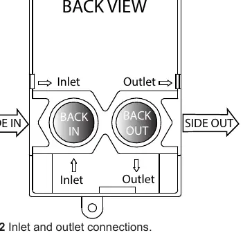
- Connect the gas supply to the inlet (ensure the arrow points into the valve).
- Connect the outlet side to the gas appliance.
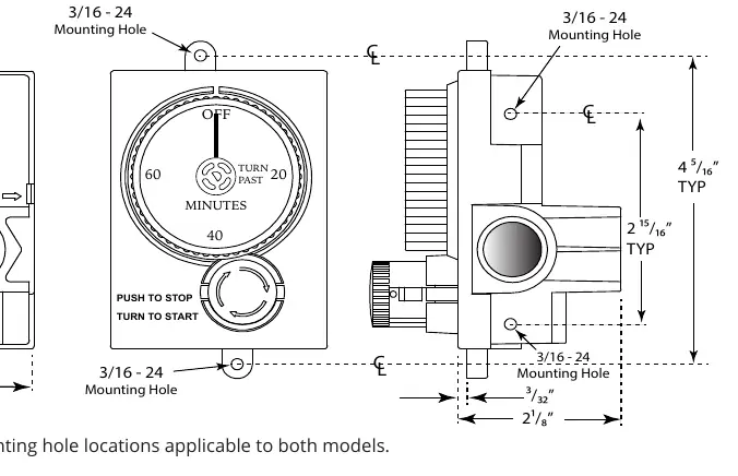
- Use the four mounting holes (two per side) or the two mounting tabs (top and bottom) to secure the unit.
- Stainless steel screws are recommended for outdoor applications.
- Perform a gas leak test immediately after plumbing is complete.
Operation
To Turn On:
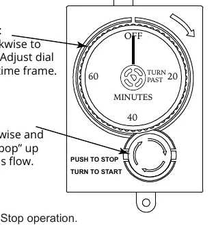
- Rotate the clear timer dial past 20 (or 0.5) to set the desired time. The timer will begin ticking.
- Turn the red knob clockwise (about a 1/4 turn) until it pops outward. Gas will now flow to the appliance.
To Turn Off:
- Let the timer expire naturally.
- Alternatively, press the red knob inward until it stops. It will lock down with a click, stopping the gas flow.
Note: Do not force the timer dial to the OFF position after the time is set, as this can weaken the internal spring and affect timing accuracy.
Troubleshooting
If you experience issues, check the following:
- No gas flow: Ensure the dial is set past the turn point, the red knob is in the outward (ON) position, the primary gas supply is on, and the inlet mesh screen is free of debris.
- Gas flow won't stop: Check if the timer is plumbed backwards, if gas pressure exceeds the 1/2 PSI maximum, or if there is physical damage to the unit.
Specifications
- Pipe Size: 1/2 inch NPT (2 inlets, 2 outlets)
- Capacity: 165,000 Btu/Hr at 1 inch Pressure Drop (NG)
- Timer Accuracy: 60 Min +/- 15%
- Ambient Temperature: 0°F to 175°F
- Gas Type: Natural or LP Gas (no conversion required)
- Certification: Tested to ANSI Z21.21; CSA 6.5
Practical help
Common problems
No gas flow
Ensure the dial is set past the turn point, the red knob is in the outward (ON) position, the primary gas supply is on, and the inlet mesh screen is free of debris.
Gas flow won't stop
Check if the timer is plumbed backwards, if gas pressure exceeds the 1/2 PSI maximum, or if there is physical damage to the unit.
Before use
- Ensure the installer is a trained, experienced service technician or gas plumber.
- Verify the gas type (Natural or LP) is compatible.
- Check that the gas pressure does not exceed 1/2 PSI.
- Perform a gas leak test after plumbing is complete.
- Ensure the unit is mounted in an upright position.
Specs in practice
- Ambient Temperature
- Operating range is 0°F to 175°F.
Images and diagrams
- Fig 1: Mounting hole locations and dimensions.
- Fig 2: Inlet and outlet connection points.
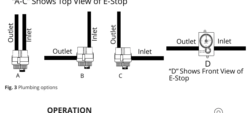
- Fig 3: Various plumbing configuration options.
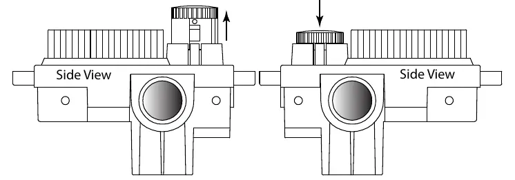
- Fig 4: Operation of the timer dial and red knob.
- Fig 5: Visual guide for red knob positions (Up = ON, Down = OFF).
Model compatibility
- Compatible with both Natural and LP Gas without conversion.
- Suitable for indoor or outdoor use.
- Designed for gas fire pits, grills, logs, and torch lights.

Manual page author
Michael Turner
Technical manual editor
Reviews PDF manuals for structure, safety notes, and practical product details so readers can find the right information quickly.