Lighting / Ceiling Fans
Installation Guide for Tidoin 900001/900002 Ceiling Lamp
Quick installation guide for Tidoin 900001 and 900002 ceiling lamps. Includes assembly steps, wiring diagrams, safety precautions, and technical specifications.
Table of contents
Manual images
Click an image to enlargeImportant Safety and Specifications
Before beginning installation, ensure the electricity is turned off at the main circuit breaker panel. Professional electrician installation is highly recommended. This product contains chemicals including lead; handle with care. The fixture is designed for a 120V, 60Hz supply circuit and requires one E26 base bulb (100W Max). The manufacturer suggests using a 9W LED ST58 bulb.
Components
Ensure all parts are present before starting assembly. The package includes:
- Canopy with swivel and mounting bracket
- Central rod, stems (6" and 12"), and square pipes
- Top and bottom frames
- Hardware: wire nuts, mounting screws, cap nuts, and screws for frame assembly
If any parts are missing or glass is damaged, contact support at [email protected].
Assembly and Installation
Follow these steps to assemble and install the fixture:
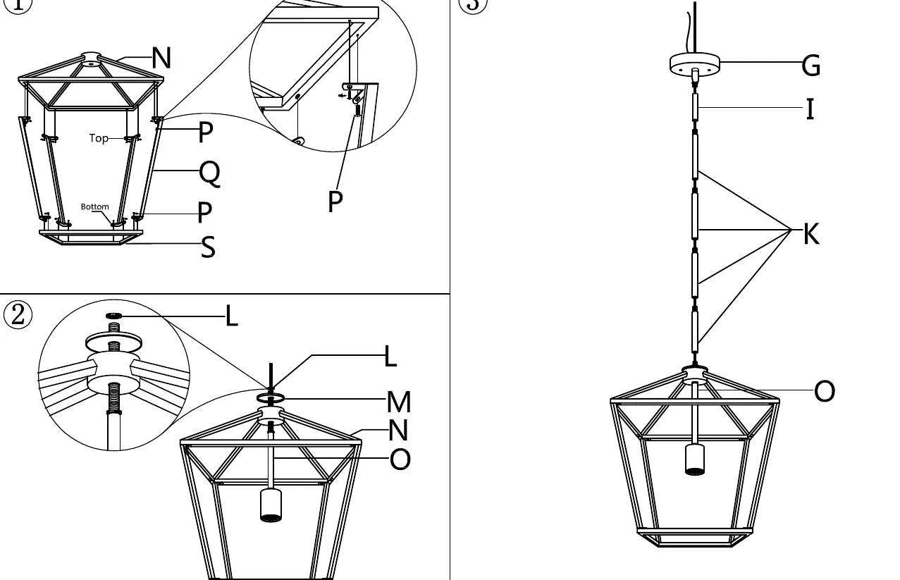
- Frame Assembly: Attach the top frame (N) to the top of the four square pipes (Q) using screws (P). Attach the bottom frame (S) to the bottom of the pipes (Q) using screws (P). Adjust for alignment and fasten all screws.
- Central Rod: Release the ring (L) from the rod (O). Insert the rod (O) into the top frame (N), slide on the cap (M), and secure with the ring (L). Feed the fixture wires (J) through the center hole.
- Height Adjustment: Determine the desired hanging height. Thread the required stems (I & K) onto the central rod (O) and attach them to the canopy swivel (G). Feed wires through the stems and canopy.
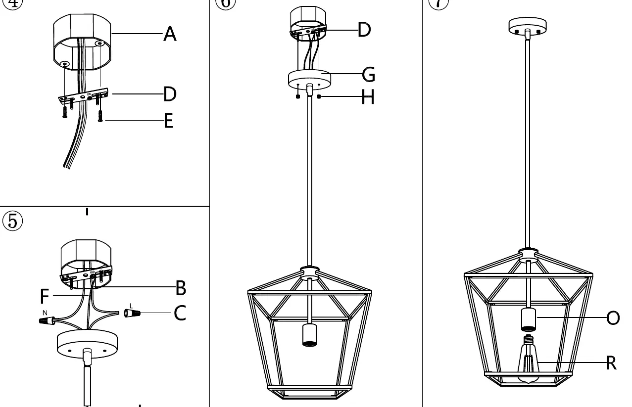
- Mounting: Adjust the studs on the mounting bracket (D) to ensure the canopy (G) fits flush against the ceiling. Attach the bracket (D) to the junction box (A) using mounting screws (E).
- Wiring: Connect the fixture wires to the supply wires according to the wiring diagram.
- Final Mounting: Slide the canopy (G) onto the mounting bracket studs and secure with cap nuts (H).
- Bulb Installation: Screw the light bulb (R) into the socket on the rod (O).
Wiring Instructions
Connect the wires as follows:
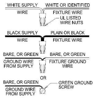
- White Supply Wire: Connect to the White or Identified fixture wire using a wire nut.
- Black Supply Wire: Connect to the Plain or Black fixture wire using a wire nut.
- Ground Wire: Connect the bare or green supply ground wire to the fixture ground wire or the green ground screw on the mounting bracket.
Practical help
Common problems
Missing parts or damaged components
Contact the manufacturer at [email protected] for replacements.
Canopy does not fit flush against the ceiling
Adjust the protrusion of the studs on the mounting bracket (D) until the cap nuts (H) secure the canopy properly.
Fixture is not level
Ensure the square pipes (Q) and frames are aligned correctly before fully tightening the screws (P).
Before use
- Turn off power at the main circuit breaker.
- Verify all components against the parts list.
- Ensure the junction box is compatible and securely mounted.
- Check that the bulb type is E26 (max 100W).
- Confirm the desired hanging height to select the correct number of stems.
Specs in practice
- 1*E26*100W Max
- The fixture requires one E26 base bulb with a maximum wattage of 100W.
Images and diagrams
- The wiring diagram illustrates standard color-coded connections: White to White, Black to Black, and Ground to Ground.
- Assembly diagrams show the sequence of connecting the frame, central rod, and canopy.
Model compatibility
- Requires a standard junction box.
- Not suitable for use with special control devices unless verified for N.E.C. compliance.

Manual page author
David Miller
Documentation analyst
Organizes user manual content into clear summaries, with attention to model details, product context, and everyday usability.