HVAC / Air Conditioners
Gas Heat Exchanger Replacement Guide for Trane 036S
Step-by-step instructions for replacing the gas heat exchanger in Trane 036S series units. Includes safety warnings, required tools, and detailed removal and installation procedures.
Table of contents
Manual images
Click an image to enlargeQuick guide from the manual
This document provides instructions for replacing the gas heat exchanger in Trane Precedent A cabinet units (3 to 5 tons). The procedure requires two people to safely remove and install the heat exchanger to prevent damage. Before beginning, ensure all electrical power and gas supplies are disconnected and locked out. The process involves removing access panels, disconnecting internal components, removing the old heat exchanger, and installing the new one with proper sealing.
Safety warnings
- Hazardous Voltage and Gas: Failure to turn off gas or disconnect power before servicing can result in explosion, electrocution, death, or serious injury.
- Flammable Refrigerant: This unit uses R-454B (A2L) flammable refrigerant. Use only R-454B rated service equipment.
- Personal Protective Equipment (PPE): Technicians must wear appropriate PPE, including cut-resistant gloves, safety glasses, and arc flash clothing when required.
- EHS Policies: Follow all company Environmental, Health, and Safety (EHS) policies and local regulations.
Tools and parts
Ensure you have the following tools and materials before starting:
- 5/16-inch Nut Driver
- 5/16-inch Nut Long Driver (12 to 15-inch)
- 5/16-inch Ratchet and Extension
- Blade/Cutter
- High-temperature RTV silicone (500°F rating, field supplied)
- Tube insulation (7/8 in. OD x 3/8 in. Thick x 18 in. Long)
Replacement procedures
- Shut off all electrical power and gas service to the unit.
- Disconnect condensate drain piping.
- Remove all access panels, front center posts, and the rear duct cover.
- If configured for horizontal supply, remove the connecting ductwork.
- Remove the condensate drain pan.
- Disconnect wires from components in the gas heat compartment (TCO1, Pressure Switch, Gas Valve, etc.) and route them out through harness holes.
- Remove the high voltage spark ignition wire and the pressure switch orange silicone hose.
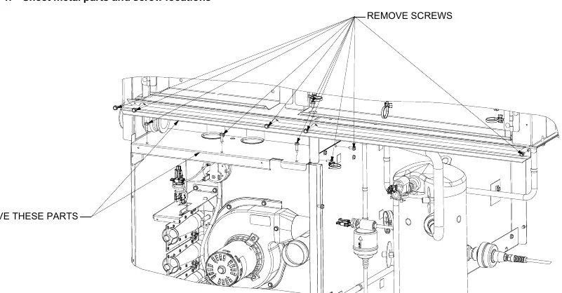
- Open the control box access panel and remove the specified sheet metal parts.
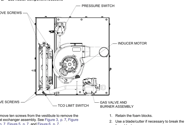
- Remove the gas valve, manifold tube, burner assembly, TCO1 limit switch, pressure switch, and inducer motor.
- Discard the old gasket behind the combustion blower and retain the air orifice.
- Remove the ten screws from the vestibule to access the heat exchanger assembly. This includes removing foam blocks covering refrigeration tubes and accessing screws from the indoor coil and compressor sides.
- Remove the heat exchanger support rod if necessary.
- With two people, push the heat exchanger out from the rear supply duct through the front of the unit.
Installation and sealing
- Install the new heat exchanger by feeding it through the front of the unit with two people, aligning it from the rear duct opening.
- Verify the heat exchanger catches the support rod between the bottom primary tube and the tube directly above it.
- Reinstall the support rod if it was removed.
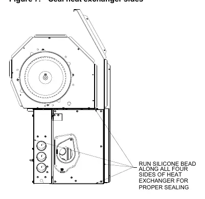
- Seal the heat exchanger with a bead of high-temperature silicone along all four sides.
- Use field-supplied tube insulation to cover the exposed rear side refrigeration tube and secure it with cable ties.
- Reinstall the sheet metal parts and components removed earlier.
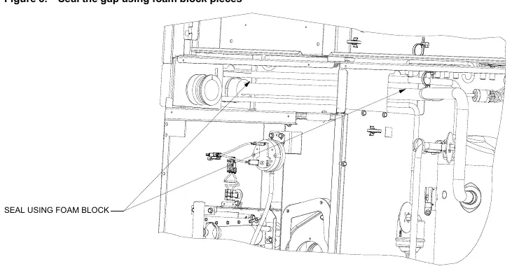
- Cut the rear foam block into small pieces (~0.5-inch thick) to seal gaps and prevent air leakage.
- Use the front foam block to cover the front tubes.
- Reassemble the unit by reversing the removal steps.
Practical help
Common problems
Hazardous gas or electrical shock risk
Turn off gas supply and disconnect all electrical power, including remote disconnects, before servicing. Follow lockout/tagout procedures.
Flammable refrigerant (R-454B) handling
Use only R-454B rated service equipment and components to avoid fire or equipment failure.
Damage to heat exchanger during removal/installation
Use two people to push and guide the heat exchanger through the unit to prevent damage.
Air leakage after installation
Ensure the heat exchanger is sealed with a bead of high-temperature silicone on all four sides and that foam blocks are cut and placed to seal gaps around tubes.
Before use
- Verify the unit model number on the nameplate.
- Ensure all electrical power and gas service are shut off.
- Gather 5/16-inch nut drivers and a ratchet extension.
- Obtain high-temperature RTV silicone (500°F rating).
- Wear required PPE (cut-resistant gloves, safety glasses, etc.).
- Ensure two people are available for the heat exchanger removal/installation.
Specs in practice
- RTV Silicone
- Must have a maximum temperature rating of 500°F.
- Tube Insulation
- Required size: 7/8 in. OD x 3/8 in. Thick x 18 in. Long.
Images and diagrams
- Figure 1 & 2: Identifies locations of screws, gas valve, burner assembly, inducer motor, and pressure switch.
- Figure 7: Shows the application of the silicone bead along all four sides of the heat exchanger for proper sealing.
- Figure 8: Illustrates how to use foam block pieces to seal gaps around tubes to prevent air leakage.
Model compatibility
- Compatible with Precedent A cabinet, 3 to 5 tons, Gas heat models.
- Model numbers include (Y, D)SK*(036-060)S(0, A)(L, M, H) and YHK*036S(0, A)(L, M, H).

Manual page author
Emily Carter
User documentation editor
Prepares concise manual descriptions and highlights the most useful setup, operation, and maintenance information for readers.