User Manual for VOLT 12/24V 20A MPPT Charge Controller
Quick guide for the VOLT 12/24V 20A MPPT Charge Controller. Includes installation steps, wiring sequence, LED status indicators, web interface configuration, and troubleshooting.
Table of contents
Manual images
Jump to the sectionQuick guide from the manual
This document provides essential instructions for the VOLT 12/24V 20A MPPT Charge Controller. It is designed for off-grid solar systems, featuring automatic 12/24V system voltage detection and an integrated web interface for monitoring and management via SNMP.
Installation
Proper installation sequence is critical to avoid damage. Always connect the battery first to allow the controller to detect the system voltage.
- Connect the battery to the controller.
- Connect the load.
- Connect the solar panel (PV).
Warning: Do not reverse the polarity of the solar panel or battery connections. Ensure the inverter or high-surge loads are connected directly to the battery, not the controller output.
LED Indicators
- Panel: Solid green (connected), Off (disconnected).
- Battery (RGB LED): Flashing green (charging), Flashing red (discharging), Solid green (charged/float), Solid red (low battery), Solid blue (short/overload).
- Output: Solid green (on), Off (off).
- Link/Act: Indicates Ethernet communication status.
Web Interface and Configuration
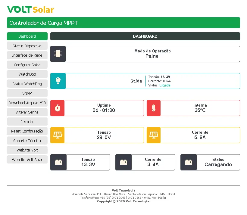
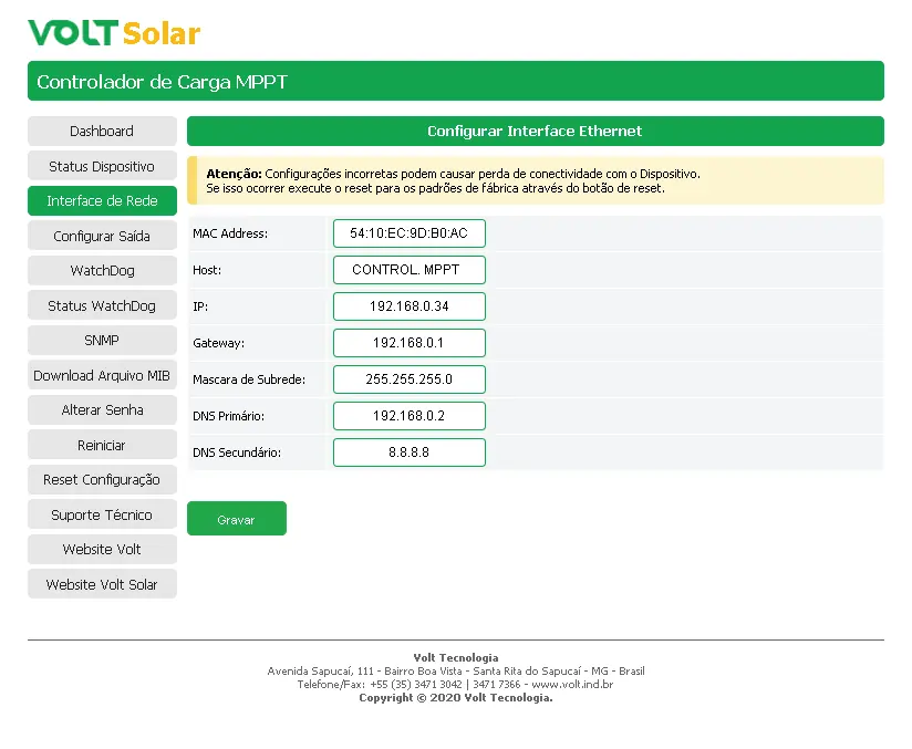
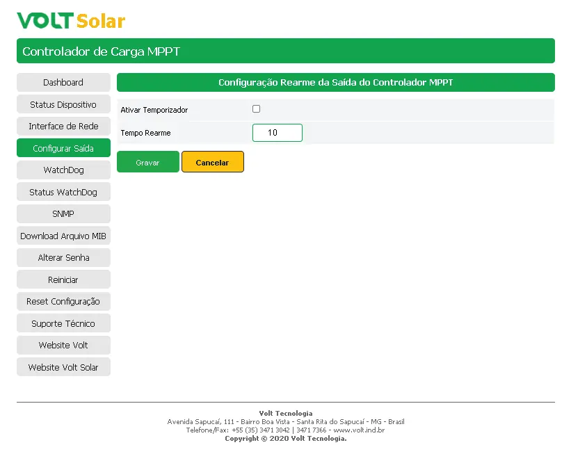
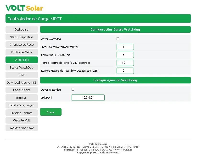
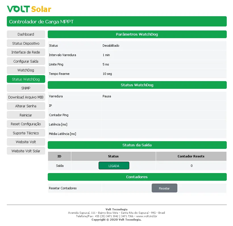
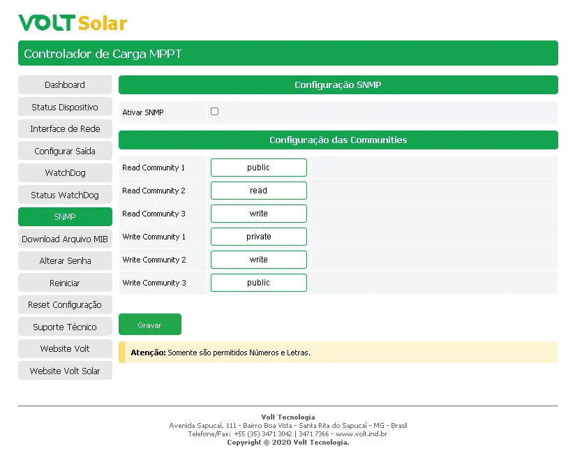
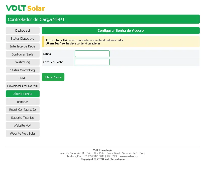
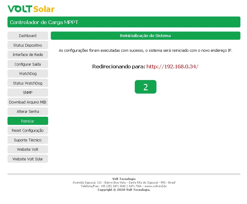
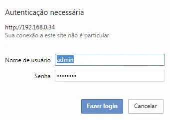
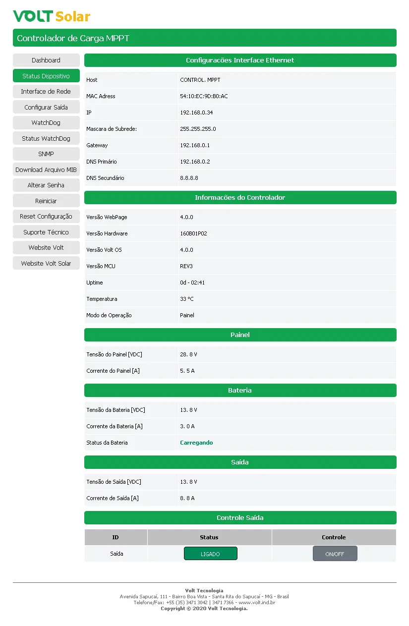
The device is accessible via a web browser using the default IP address 192.168.0.34. Default login credentials are: Username admin, Password voltvolt. The interface allows for network settings, watchdog configuration, output control, and real-time monitoring of system parameters.
Protection Features
- Reverse polarity protection for PV and battery.
- Overload and short-circuit protection for the output.
- Low voltage disconnect (10.5V for 12V systems / 21.0V for 24V systems).
- Automatic output re-arming after low voltage recovery (12.6V / 25.2V).
Technical Specifications
- Max PV Voltage: 50Vdc.
- Max Load Current: 20A.
- Operating Temperature: 0 to 60°C.
- Dimensions: 71 x 212 x 87 mm.
- Weight: 800g.
Practical help
Common problems
Disconnect the battery and verify all wiring connections for correct polarity.
Ensure the computer is on the same network range. If necessary, perform a physical reset by holding the Function button for 10 seconds until the battery LED turns blue.
Clear the short circuit and manually toggle the output using the ON/OFF function in the web interface or the physical button.
Before use
- Verify battery voltage (12V or 24V).
- Ensure solar panel open circuit voltage does not exceed 50Vdc.
- Check that all cables are securely fastened to the terminal blocks.
- Confirm the computer network settings match the default IP 192.168.0.34.
Specs in practice
- MPPT Technology
- Maximum Power Point Tracking optimizes solar energy collection, increasing efficiency by 20-30% compared to PWM controllers.
- Positive Common
- The controller uses a positive common architecture for its electrical connections.
Images and diagrams
- The installation diagram shows the correct sequence: 1. Battery, 2. Load, 3. PV.
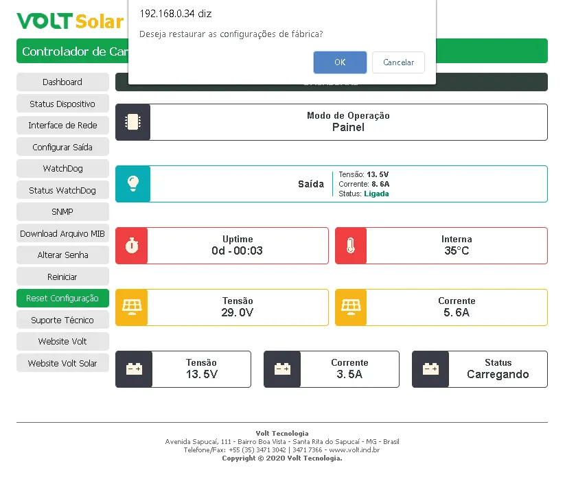
- The dashboard view displays real-time voltage, current, uptime, and internal temperature.
Model compatibility
- Compatible with browsers supporting HTML5 and Javascript.
- Supports SNMP protocol for management software like The Dude, Zabbix, Nagios, PRTG, and NetXMS.

Manual page author
David Miller
Documentation analyst
Organizes user manual content into clear summaries, with attention to model details, product context, and everyday usability.