HVAC / Condensate Pumps
Wilo-Plavis Condensate Lifting Unit Installation and Operating Instructions
Quick guide for the Wilo-Plavis condensate lifting unit. Includes installation, electrical connection, maintenance, troubleshooting, and technical specifications for models 011-C, 013-C, and 015-C.
Table of contents
Manual images
Click an image to enlargeQuick guide from the manual
This document provides essential information for the installation, operation, and maintenance of the Wilo-Plavis condensate lifting unit. The unit is designed to pump condensate from boilers, air-conditioning systems, refrigeration systems, and air dehumidifiers. Ensure the unit is installed horizontally on a level surface and that all electrical connections are performed by a qualified electrician.
Product description
The Wilo-Plavis series (011-C, 013-C, 015-C) is designed to collect and pump condensate that cannot be drained by gravity. The system features an automatic liquid level control, a non-return valve, and an alarm probe (depending on the model) to signal defects.
Installation
Mechanical Installation: Place the unit horizontally on a level surface in a dry, well-ventilated, and frost-free location. Do not install anything underneath the unit to prevent damage in case of overflow. Secure the unit to the wall using the provided mounting points if necessary.
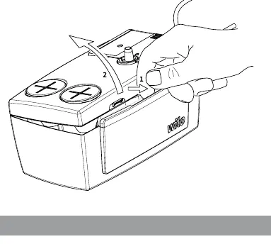
Piping Connection: Connect the inlet pipes to the input holes and the drainage pipe to the non-return valve. Ensure the drainage pipe is not kinked or bent, with a bending radius greater than 60 mm.
Electrical Connection: The system must be connected to a circuit with a residual current device (RCD) not exceeding 30 mA. Ensure the power supply matches the rating plate specifications.
Commissioning
Perform a function check by filling the tank with clear water. Verify that the pump starts when the high-level probe is reached and stops when the low-level probe is reached. For models 013-C and 015-C, test the alarm function by filling the tank until it overflows.
Maintenance
Regular maintenance is required to ensure reliable operation:
- Cleaning the tank: Regularly clean the interior of the tank and check the probes for dirt.
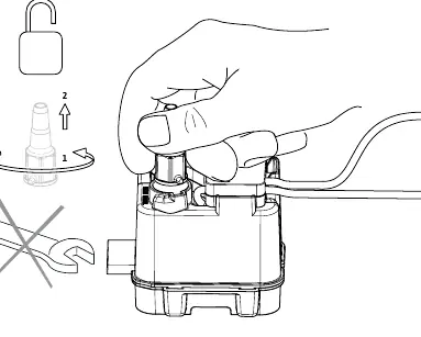
- Non-return valve: Periodically check the non-return valve and the underlying gasket for blockages. Do not open the valve.
- Neutralization (Model 015-C): If using the pH-neutralization granulate, handle it with care, wearing gloves and safety glasses, as it is an irritant.
Troubleshooting
If the product fails to start, check the power supply and ensure the probes are clean. If the product does not drain, check for blockages in the inlet or drainage pipes. If the alarm is activated, verify the condensate drainage and check the alarm switch position (NC/NO).
Safety
Always wear protective gloves and glasses when performing maintenance, especially when handling condensate from boilers, which is acidic. Ensure the unit is disconnected from the power supply before any maintenance work.
Practical help
Common problems
Product will not start
Check power supply connection and voltage. Ensure probes are clean and not clogged.
Product will not drain
Check inlet and drainage pipes for blockages or kinks. Ensure the non-return valve is not blocked.
Alarm is activated
Check if condensate is being drained. Verify the alarm switch position (NC or NO) matches the desired function.
Product starts too often
Check if the non-return valve is closing properly. Ensure the unit is not tilted too far.
Before use
- Check for transport damage upon receipt.
- Ensure the installation surface is horizontal and level.
- Verify that the power supply voltage matches the rating plate.
- Ensure inlet and drainage pipes are free of kinks.
- Check that the non-return valve is clear of debris.
Show more Show less
Specs in practice
- Delivery head
- The maximum height the pump can lift the condensate (4 m).
- Protection class
- IP X4, indicating protection against splashing water.
- Admissible fluid
- pH > 2.5; condensate must not be highly acidic.
- Ambient temperature
- Operating range between +5 °C and +40 °C.
Images and diagrams
- Fig 1: Dimensions and installation overview.
- Fig 3: Component identification and connection points.
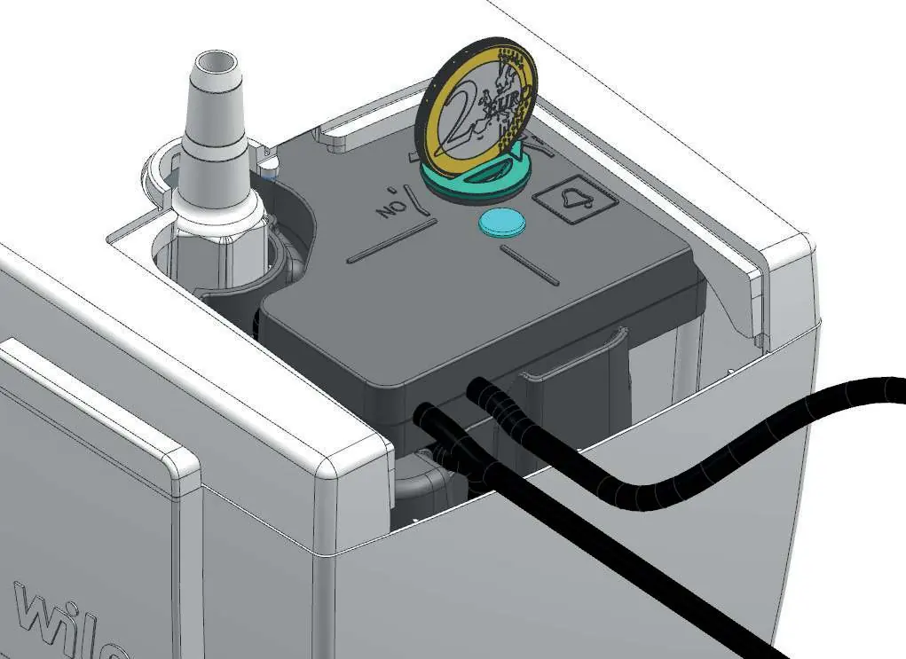
- Fig 4: Alarm switch adjustment and probe locations.
- Fig 8: Non-return valve maintenance.
Model compatibility
- Suitable for boilers, air-conditioning, refrigeration, and dehumidifiers.
- Not suitable for flammable or explosive liquids.
- Condensate from boilers may require neutralization.

Manual page author
David Miller
Documentation analyst