Furniture / Storage Cabinets
StarTech.com 12HE Wall-Mounted Network Cabinet with Hinged Back Panel User Guide
Quick guide for the StarTech.com 12HE wall-mounted network cabinet. Includes installation, grounding, door reversal, and rail adjustment instructions.
Table of contents
Manual images
Jump to the sectionQuick guide from the manual
This document provides essential instructions for the safe installation and configuration of the StarTech.com 12HE wall-mounted network cabinet (RK12WALHM). The cabinet is designed for professional network equipment storage and requires proper wall mounting and grounding for safety. Always ensure the wall structure can support at least four times the total weight of the cabinet and installed equipment.
Safety warnings
- The cabinet is extremely heavy; do not attempt to lift or move it without assistance.
- Ensure the wall structure and mounting hardware are appropriate for the installation.
- Do not extend more than one component at a time to prevent tipping.
- Keep liquids away from the cabinet.
- The product must be grounded; do not use without a protective earth connection.
- Load the heaviest equipment at the bottom of the cabinet first.
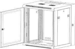
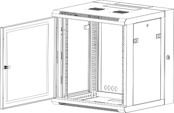
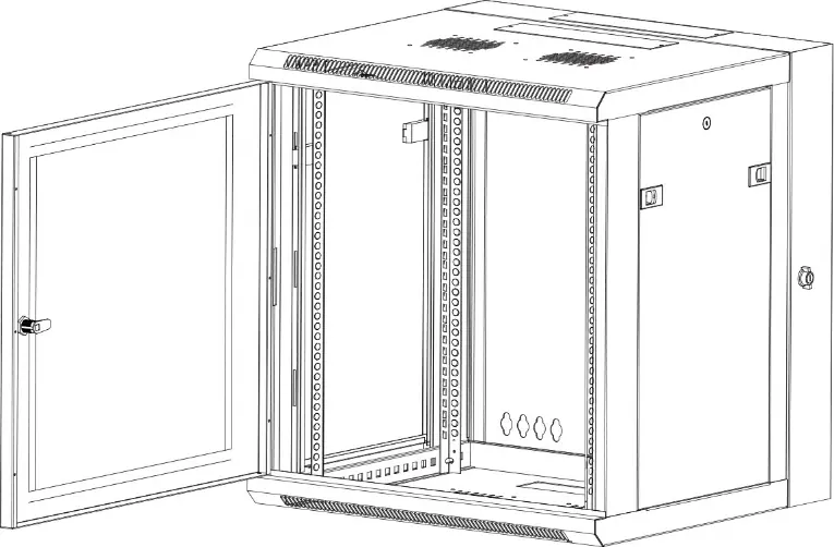
Product components
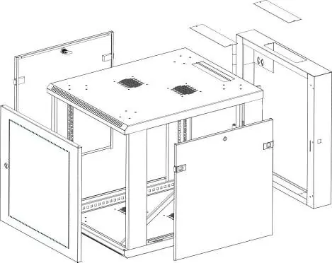
- Front and rear doors
- Horizontal and vertical mounting rails
- Cable access openings with covers
- Side panels
- Ventilation ports
Installation and setup
Wall mounting: Remove all equipment before mounting. Use appropriate hardware for your wall type. Each mounting hole can accommodate M8, M10, 5/16", or 3/8" screws.
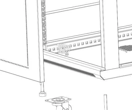
Grounding: Use an M6 screw to attach a grounding cable to the front or rear grounding point. Route the cable under the frame and connect it to your facility's earth connection.
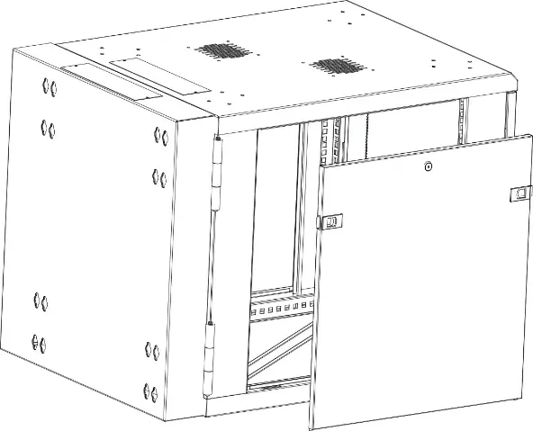
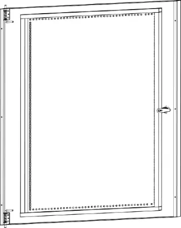
Door reversal: The front door can be reversed to open from the left or right. Use the levers at the top and bottom of the door to release it from the hinges, flip it, and re-insert the levers into the hinge holes on the opposite side.
Adjusting mounting rails: Rails can be adjusted in 20 mm (3/4 inch) increments. Remove the screws and cage nuts at the top and bottom of the rails, move them to the desired depth, and re-secure them. Rails can also be flipped to face the threaded holes toward the front.
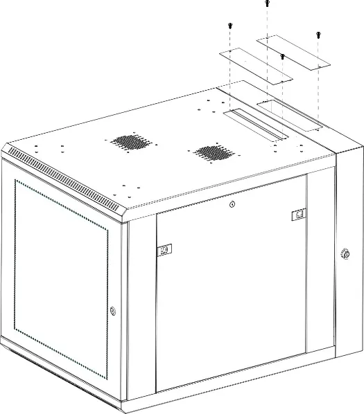
Cable access: Remove the two screws at the ends of the cable access covers to open the cable management ports.
Maintenance
Side panels can be removed by unlocking them, pulling the two tabs toward the center of the panel, and lifting the panel away from the cabinet. To reinstall, seat the panel in the bottom groove, pull the tabs, press the top into the frame, and lock.
Official resources from the manual
Practical help
Common problems
Cabinet is unstable or tipping
Ensure only one component is extended at a time and that the heaviest equipment is installed at the bottom.
Difficulty mounting equipment
Ensure cage nuts are properly installed in the mounting rails and that the rails are adjusted to the correct depth for your specific device.
Door does not open in the desired direction
Follow the door reversal procedure by releasing the top and bottom levers to flip the door orientation.
Before use
- Verify wall structure can support 4x the total weight of the cabinet and equipment.
- Ensure you have a Phillips head screwdriver.
- Confirm you have appropriate wall mounting hardware for your specific wall type.
- Check that the grounding cable is ready for connection.
- Ensure you have assistance for lifting the cabinet.
Specs in practice
- Weight capacity
- The cabinet can support up to 90 kg (198 lb) of equipment.
- Rail adjustment
- Rails can be moved in 20 mm (3/4 inch) increments.
Images and diagrams
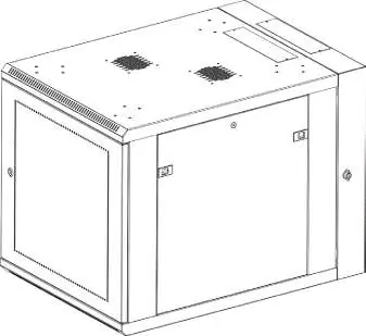
- The product diagram identifies the front/rear doors, mounting rails, and cable access points.
- Grounding points are located on the frame for secure earth connection.
- Side panel removal uses a two-tab release mechanism.
Model compatibility
- Mounting holes accept M8, M10, 5/16", or 3/8" screws.
- Always check the documentation of the equipment you are installing for specific mounting hardware requirements.

Manual page author
Michael Turner
Technical manual editor
Reviews PDF manuals for structure, safety notes, and practical product details so readers can find the right information quickly.