Health / Medical Dressings
Operator's Manual for 3M Dynatel 1420-iD Marker Locator
Quick guide for the 3M Dynatel 1420-iD and 1420E-iD Marker Locator. Learn how to install batteries, configure E-models, locate markers, create templates, write/read iD markers, and use GPS features.
Table of contents
Manual images
Click an image to enlargeQuick Guide
The 3M Dynatel 1420-iD and 1420E-iD are electronic marker locators designed to locate, read, and write information to 3M iD Markers. For E-Model (Export) units, an initial configuration via PC Tools software is required before use. Ensure the unit is configured for the specific country of operation to comply with local regulations.
Safety Information
Always follow safety guidelines to prevent electric shock or injury. Do not operate the unit in countries with non-specific configuration settings. The device is designed for locating buried markers; use only as specified to maintain safety protections.
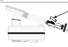
Battery Installation
The unit uses 8 'AA' (LR 6) Alkaline batteries. To install: twist the cap to open the battery compartment, slide the compartment out of the handle, and insert batteries observing correct polarity. Always remove batteries when storing the unit for long periods.
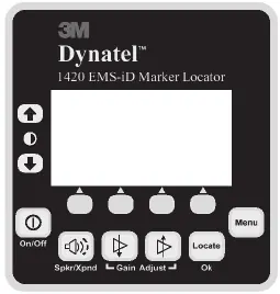
Keypad and Display
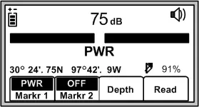
The interface includes a power button, volume control, gain adjustment, and soft keys (yellow) whose functions change based on the current mode. The display shows signal strength, battery level, and operational data. Use the Menu button to access configuration settings, including clock, language, and marker types.
Locating Markers
To locate markers, press the Locate/OK button. Enable desired marker types in the Setup menu. For single marker locate, select the utility type and adjust the Gain until the bar graph opens. When a marker is detected, the signal strength will be at its maximum. For dual marker locate, select two utility types and follow the same procedure.
iD Marker Operations
Creating Templates: Use the User Template screen to create or edit templates for writing to iD markers. It is recommended to create templates using the 3M Dynatel PC Tool Kit software and download them to the locator.
Writing to Markers: Select a template, configure write options (Overwrite, X-Type, Marker type, Lock/Unlock), and hold the locator over the marker. Ensure the locator is within the maximum writing range (e.g., 6 inches for Near-Surface, 12 inches for Ball, 24 inches for Full-Range).
Reading Markers: Lower the locator tip to the ground over the marker and press Read. The locator will display the marker's data, which is automatically saved to the Read History.
GPS Compatibility
The locator can communicate with GPS devices via the Serial Port. Configure the COM Setup to NMEA (to receive coordinates) or GIS (to send/receive data). When connected, marker data can be stamped with latitude, longitude, and date/time information for mapping purposes.
Maintenance and Self Test
Clean the unit with a damp cloth. Use the Self Test mode in the menu to verify unit information, including serial number, software revision, and hardware revision.
Manufacturer information
3M
Practical help
Common problems
No ID Marker Found
Verify if it is a passive marker or if the wrong frequency is selected.
Incompatible marker
The X-Type marker option may be set incorrectly. Check if the marker serial number ends with an 'X' (Gen 2) and adjust the setting accordingly.
Insert External Device
The GPS device is not configured properly, or there is an error communicating with the locator.
Before use
- Install 8 'AA' (LR 6) Alkaline batteries with correct polarity.
- For E-Models, perform initial configuration using 3M Dynatel PC Tools software.
- Ensure the locator is set to the correct country configuration.
- Enable the required marker types in the Setup menu.
- Check that the Gain level is set high when scanning for markers.
Specs in practice
- Near-Surface iD Marker Writing Range
- 6 in (15 cm) maximum
- Ball iD Marker Writing Range
- 12 in (30 cm) maximum
- Full-Range iD Marker Writing Range
- 24 in (61 cm) maximum
- Operating Temperature
- -20°C to 50°C (-4°F to 122°F)
- Environmental Standard
- IP54
Images and diagrams
- Keypad layout showing power, volume, gain, and menu buttons.
- Display screen showing signal strength, battery level, and marker mode.
Model compatibility
- 1420E-iD requires initial country configuration via PC.
- Compatible with hand-held GPS devices for coordinate mapping.
- Supports RS232 serial connection to PC for software upgrades and template management.

Manual page author
Michael Turner
Technical manual editor
Reviews PDF manuals for structure, safety notes, and practical product details so readers can find the right information quickly.