Industrial / Process Controllers
Technical Specifications for Allen Bradley 1756 ControlLogix Chassis
Access detailed technical specifications, mounting dimensions, and installation clearance requirements for the Allen Bradley 1756 ControlLogix chassis series. This guide covers standard, XT, and ZXT models, including environmental ratings...
Table of contents
Manual images
Click an image to enlargeQuick Guide to ControlLogix Chassis Specifications
This document provides technical data for the 1756 ControlLogix chassis, a modular system designed for horizontal back-panel mounting. The chassis provides a high-speed communication path between modules and distributes power. Users should refer to this guide for mounting dimensions, spacing requirements, and environmental specifications to ensure proper installation and operation.
Chassis Specifications
The ControlLogix chassis are available in various slot configurations (4, 7, 10, 13, 17 slots). Key technical attributes include:
- Backplane Current: Varies by voltage (1.2V DC, 3.3V DC, 5.1V DC, 24V DC).
- Power Dissipation: Ranges from 4W to 6W depending on the chassis model.
- Mounting Method: Horizontal only.
- Location: Panel mount.
- Wire Size: Functional earth ground (8.3 mm2 / 8 AWG) and Protective earth ground (2.1 mm2 / 14 AWG) using copper wire rated at 90 C or greater.
Environmental Specifications
The chassis are designed for industrial environments. Standard chassis operate between 0 and 60 C (Series B) or -25 and 60 C (Series C). ControlLogix-XT chassis support extreme environments, operating from -25 to 70 C. Both types support 5 to 95% noncondensing relative humidity and are rated for specific vibration and shock levels (e.g., 2g vibration, 30g operating shock).
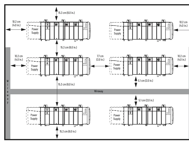
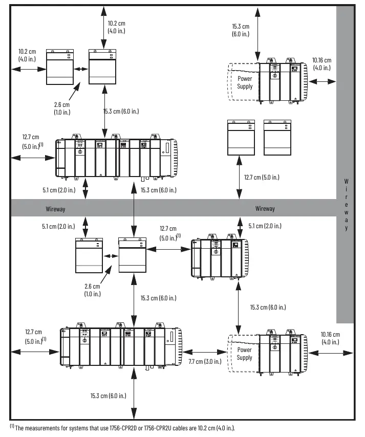
Spacing and Clearance Requirements
Proper clearance is critical for airflow and cable management. The 1756-CPR2 cable requires a minimum clearance of 12.7 cm (5.0 in.) on the left side of the chassis for routing. Redundant power supplies also require a minimum clearance of 12.7 cm (5.0 in.) below the supply for cable connection. Always maintain the specified spacing from wireways and other components to ensure compliance and system longevity.
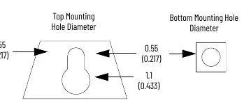
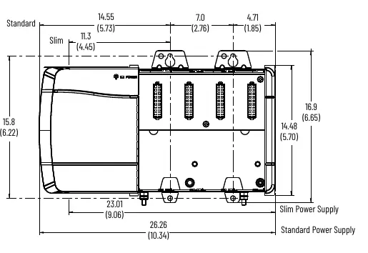
Mounting Dimensions
The manual provides detailed dimensional drawings for all chassis models, including Series B, Series C, and XT/ZXT variants. These drawings specify the top and bottom mounting hole diameters (0.55 cm and 1.1 cm) and the overall dimensions (height, width, depth) for each specific chassis configuration. Users must consult the specific page corresponding to their chassis model (e.g., 1756-A4/B, 1756-A17/C) for accurate drilling and mounting templates.

Certifications and Compliance
The ControlLogix chassis meet various international standards, including c-UL-us, FM, CE, RCM, Ex, IECEx, UKEx, UKCA, KC, CCC, and Moroccan regulations. These certifications confirm the equipment is suitable for use in industrial control environments, including Class I, Division 2 hazardous locations where applicable.
Accessories
Slot filler modules are available to cover empty slots in the chassis. Use 1756-N2 for standard ControlLogix chassis and 1756-N2XT for ControlLogix-XT and ControlLogix-ZXT chassis.
Manufacturer information
Allen-Bradley
Practical help
Common problems
Insufficient clearance for cables
Ensure a minimum of 12.7 cm (5.0 in.) clearance on the left side of the chassis for 1756-CPR2 cable routing and below redundant power supplies.
Corrosion in extreme environments
For ISA G3 or GX environments, ensure the use of conformally coated XT or ZXT chassis and keep port plugs/covers installed in unused ports.
Before use
- Verify the specific chassis model (Series B, C, or XT) matches the application requirements.
- Ensure the mounting surface is suitable for horizontal back-panel mounting.
- Check that the cabinet size meets the minimum dimensions specified for the chassis model.
- Verify that the wire size for earth ground meets the 8 AWG and 14 AWG requirements.
- Confirm that all necessary slot fillers (1756-N2 or 1756-N2XT) are available for empty slots.
Specs in practice
- Backplane current
- The maximum current the chassis backplane can supply to modules per slot at specific voltages.
- Power dissipation
- The maximum heat energy generated by the chassis, used for cabinet cooling calculations.
- Conformal Coated
- A protective coating applied to the circuit board to resist corrosion and environmental contaminants.
Images and diagrams
- Spacing diagrams illustrate the required distances from wireways and other components to ensure proper airflow and cable bend radius.
- Mounting hole diagrams provide the exact diameter and spacing for the top and bottom mounting tabs.
Model compatibility
- Series B and Series C chassis have different temperature ratings and environmental specifications.
- ControlLogix-XT and ZXT chassis are specifically designed for extreme temperatures and corrosive environments.
- Redundant power supply configurations require specific clearance measurements different from non-redundant setups.

Manual page author
David Miller
Documentation analyst
Organizes user manual content into clear summaries, with attention to model details, product context, and everyday usability.