Industrial / Process Controllers
User Manual for DEMA 0960.NANOC Conductivity Controller
Quick guide for the DEMA 0960.NANOC Conductivity Controller. Learn about installation, wiring, menu navigation, conductivity sampling methods, calibration, and maintenance procedures.
Table of contents
Manual images
Click an image to enlargeQuick guide from the manual
The 0960.NANOC is a microprocessor-based controller designed for irrigation water systems to automate conductivity control and chemical dosing. This manual provides instructions for installation, operation, and maintenance. Always disconnect power before opening the front panel or performing wiring.
Installation and Wiring
The controller operates on 100-240 VAC. It should be connected to an isolated circuit breaker with a true earth ground. Avoid mounting in locations with direct sunlight, extreme temperatures (below 0°F or above 120°F), or high vibration.
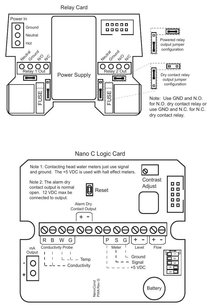
- Wiring: Prewired units include a 16 AWG power cord and 18 AWG relay output cords. Conduit units are provided with liquid-tight fittings.
- Safety: Never run low voltage signal wires (probes, flow switches, water meters) in the same conduit as high voltage (115VAC) wires.
- Relay Configuration: The relay card supports both powered relay output and dry contact relay output, configurable via jumpers.
Front Panel and Operation
The controller features a keypad for navigation and three modes of operation:
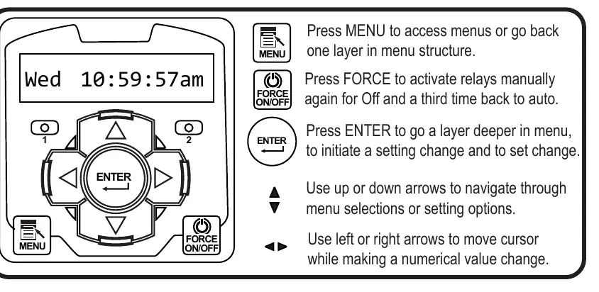
- Run: Normal operation mode. Displays system values. Returns to this mode automatically after 3 minutes of inactivity.
- Menu: Used to adjust settings. Press MENU to access, use arrows to navigate, and ENTER to select.
- Force: Allows manual activation of relays. Press FORCE to toggle relays on/off or return to auto.
Conductivity Sampling Methods
The controller offers three methods for sampling conductivity:
- Continuous: Constantly reads the sensor and activates the relay based on set points and differentials. Recommended for most irrigation systems.
- Timed Sampling: Samples at periodic intervals. The pump relay turns off at the end of the sample duration if the reading is below the set point.
- Sample and Hold: Samples at intervals, then holds the blowdown valve closed for a set period to allow for stabilization before checking conductivity again.
Calibration
The controller updates conductivity readings every two seconds. To calibrate:
- Ensure the conductivity scale is set so the setpoint is near the middle of the range.
- For continuous sampling, calibrate with the probe in a steady stream of water.
- For Timed or Sample and Hold methods, use the calibration menu to force the pump relay on to ensure a fresh sample before calibrating.
- If the conductivity scale is changed, you must reset the calibration in the Diagnostics menu.
Maintenance
The primary maintenance task is cleaning the conductivity electrode. If the unit fails to calibrate, the electrode is likely dirty.
- Cleaning Procedure: Record the current reading, turn off water flow, remove the electrode, and clean the metal tips with a clean cloth and mild cleaning solution. For scale deposits, use a mild acid solution.
- Verification: After cleaning and reinstalling, record the new reading. If a change is observed, the electrode was dirty. If no change occurs, cleaning may be needed less frequently.
Troubleshooting
If the unit displays false readings, clean the electrode or calibrate the unit. If there is no system power, check the power source, fuse, and ribbon cable connections. If outputs are not energized, check for no flow conditions or clogged pipes.
Practical help
Common problems
False reading
Clean the electrode as needed or calibrate the unit.
Will not calibrate
Clean the electrode, replace the electrode if faulty, or check wiring to the electrode.
No system power
Check power source, replace fuse if blown, and ensure ribbon cables are secure.
Outputs not energized
Check for no flow conditions, clogged pipes, or strainers; check fuse.
Before use
- Ensure the mounting surface is stable and vertical.
- Verify the power supply is within the 100-240 VAC range.
- Confirm that low voltage signal wires are not run in conduit with high voltage wires.
- Ensure the ground is a true earth ground, not shared.
- Verify the electrode is installed in a steady stream of water with no air present.
Specs in practice
- Conductivity Control
- Monitors Total Dissolved Solids (TDS) in irrigation water in MicroSiemens/cm.
- Relay Outputs
- Two mechanical relays with normally open/closed contacts for controlling external devices.
Images and diagrams
- The Logic and Relay Cards diagram illustrates terminal connections for power, relays, conductivity probe, and digital inputs.
- The Front Panel diagram shows the keypad layout, including MENU, FORCE, and navigation arrows.
Model compatibility
- Compatible with contacting head or hall effect water meters.
- Hall effect meters requiring +12 VDC need an external power supply (TFS-PWR).
- Optional 4-20mA output is available.

Manual page author
David Miller
Documentation analyst
Organizes user manual content into clear summaries, with attention to model details, product context, and everyday usability.