Home / Electrical Accessories
BG Electrical 887-01 100W Fan Controller
Quick guide for the BG Electrical 887-01 100W Fan Controller. Includes wiring instructions, installation steps, operation modes, technical specifications, and maintenance advice.
Table of contents
Manual images
Click an image to enlargeQuick guide from the manual
This document provides installation and operation instructions for the BG Electrical 887-01 100W Fan Controller. For your safety, this product must be installed in accordance with local Building Regulations by a competent person. Always isolate the power at the consumer unit before starting any work.
Installation
Replacing an existing accessory:
- Isolate the power at the consumer unit.
- Note the cable connections.
- Unscrew the accessory from the wall or mounting box.
- Disconnect the wires.
New installation:
- Install a mounting box (flush or surface) of the appropriate size.
- Select the entry point for cables and fit a grommet if using a metal box.
- Prepare cables so the conductor length reaches the terminals.
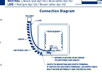
- Connect wires to the matching terminals as shown in the wiring diagram. Ensure the earth connection is made between the mounting box earth terminal and the accessory earth terminal.
- Carefully position the accessory into the box, ensuring no wires are trapped.
- Secure with screws (do not overtighten).
- Replace the fuse or reset the MCB and switch the power back on.
Operation
The fan controller features four speed settings:
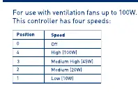
- Position 0: Off
- Position 4: High (100W)
- Position 3: Medium High (45W)
- Position 2: Medium (20W)
- Position 1: Low (10W)
Care and Maintenance
To maintain the decorative finish, clean the front face periodically with a soft cloth. Avoid using the following substances, as they may degrade the lacquer or plated finish:
- Adhesive tape (including low tack masking tape)
- Solvents
- White spirit
- Multi-surface cleaners
- Industrial multipurpose cleaning wipes
- Wet wipes
Technical Specifications
- Voltage: 220-240V AC
- Frequency: 50/60Hz
- Max Fan Load: 100W
- Terminal Capacity: 2 x 1.5mm² or 1 x 2.5mm²
- Min Box Depth (profiled plates): 25mm
- Min Box Depth (flat plates): 35mm
Manufacturer information
BG Electrical
Practical help
Common problems
Decorative finish degradation
Avoid using solvents, white spirit, abrasive cleaners, or wet wipes on the front plate.
Controller not functioning
Check that the power is switched on at the consumer unit and that all wiring connections are secure and correct.
Before use
- Ensure power is isolated at the consumer unit before starting work.
- Verify the fan load does not exceed 100W.
- Ensure the mounting box depth is sufficient (25mm for profiled, 35mm for flat).
- Confirm installation is performed by a competent person in accordance with IET regulations.
- Ensure earth connection is made between the mounting box and the accessory.
Specs in practice
- Max Fan Load
- The maximum power rating of the fan that can be controlled is 100W.
- Terminal Capacity
- The terminals accept either two 1.5mm² cables or one 2.5mm² cable.
Images and diagrams
- The wiring diagram illustrates the connections for Earth, Live, Switched Live, and Load.
- It highlights the requirement to add brown sleeving to switched live cables.
Model compatibility
- Requires a minimum box depth of 25mm for profiled plates.
- Requires a minimum box depth of 35mm for flat plates.

Manual page author
David Miller
Documentation analyst
Organizes user manual content into clear summaries, with attention to model details, product context, and everyday usability.