Home / Electrical Accessories
User Manual for BG Electrical Time Controlled 13A Socket WP23TM24
Quick guide for the BG Electrical Time Controlled 13A Socket (WP23TM24). Includes installation steps, wiring diagrams, timer operation, and safety instructions for outdoor use.
Table of contents
Manual images
Click an image to enlargeQuick guide from the manual
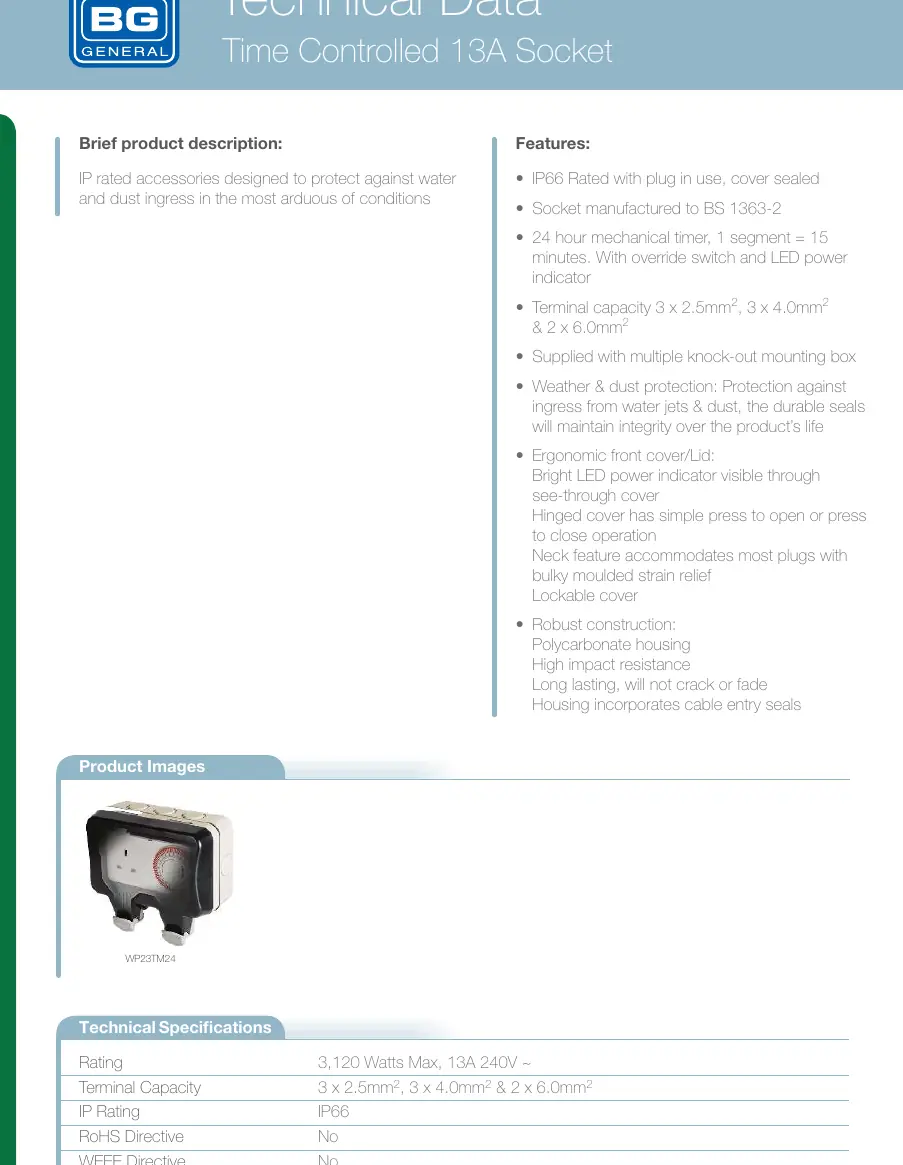
The BG Electrical Time Controlled 13A Socket (WP23TM24) is an IP66-rated outdoor power point featuring a 24-hour mechanical timer. It is designed to protect against water and dust ingress. Key operations include setting the timer by pushing segments (1 segment = 15 minutes) and using the override switch to toggle between ON, TIMER, and OFF modes.
Product Overview
The socket is constructed from high-impact polycarbonate and includes a hinged, lockable cover. It is rated for 3,120 Watts Max (13A 240V). The unit features a 24-hour mechanical timer with an override switch and LED power indicator.
Safety Warnings
- Ensure the electrical supply is switched off at the mains before commencing any work.
- Wiring must comply with the latest edition of IEE regulations (BS 7671).
- The unit must not be left with the cover raised open or the catch unlocked to maintain IP66 protection.
- Unused cable entries must have blank plugs fitted.
- Do not use solvent-based cleaners; clean only with a damp cloth and mild detergent.
Installation Instructions
The unit must be mounted on a clean, rigid, vertical surface. If the surface is uneven, it may cause product damage.
- Remove fixing screws and separate the front assembly from the rear box.
- Drilling Drain Holes: For side, top, or rear entry, the lowermost drain hole MUST be drilled out using a 5mm drill. Only one drain hole should be drilled. For bottom entry, do not drill the rear box; drill the lower-most point of the conduit run instead.
- Mount the rear box using No.8 screws in the provided fixing holes.
- Make cable entries as required, removing only necessary blank plugs.
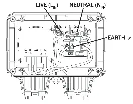
- Strip outer insulation (10-12mm) and connect wires to the terminals: Live (Brown) to LIN, Neutral (Blue) to NIN, and Earth (Green/Yellow) to E.
- Ensure all terminal screws are tight and wires are neatly routed.
- Refit the front assembly, ensuring the gasket seal is properly fitted. Do not overtighten screws.
24 Hour Timer User Instructions
- Plug the appliance into the socket.
- Push the segments on the timer face towards the outer edge for the desired operating times (1 segment = 15 minutes).
- Turn the disk clockwise until the marker points to the current time.
- Set the switch next to the disk to the centre position to activate the timer.
- Use the top position for manual override (permanently ON) or the bottom position (permanently OFF).
Manufacturer information
BG Electrical
Practical help
Common problems
Socket not working
Check if the override switch is set to 'TIMER' or 'ON' and ensure the mains supply is switched on.
Water ingress
Ensure the drain hole is drilled at the lowest point, the cover is locked, and the gasket seal is properly fitted.
Timer not functioning
Ensure the disk has been turned clockwise to the current time and the switch is set to the centre (TIMER) position.
Before use
- Ensure mains power is switched off at the consumer unit.
- Verify the mounting surface is flat and rigid.
- Check that the correct cable type (e.g., rubber insulated) is used for outdoor installation.
- Ensure the gasket seal is properly fitted over the front edge of the rear box.
- Drill the appropriate drain hole (5mm) based on the cable entry position.
Specs in practice
- Timer Segment
- 1 segment equals 15 minutes of operation
Images and diagrams
- Wiring Diagram: Shows connections for Live (Brown), Neutral (Blue), and Earth (Green/Yellow) terminals.
- Mounting Diagram: Indicates the locations for drain holes and cable entry points on the rear box.
Model compatibility
- Suitable for outdoor use with appropriate cable glands.
- Not recommended for use with unprotected flat PVC insulated cable.
- Compatible with most plugs with bulky moulded strain relief.

Manual page author
David Miller
Documentation analyst
Organizes user manual content into clear summaries, with attention to model details, product context, and everyday usability.