Tools / Power Tools
Bosch GSA 18V-24 Reciprocating Saw Spare Parts Diagram
Quick reference guide for the Bosch GSA 18V-24 reciprocating saw, featuring an exploded view diagram for component identification and maintenance.
Table of contents
Quick guide from the manual
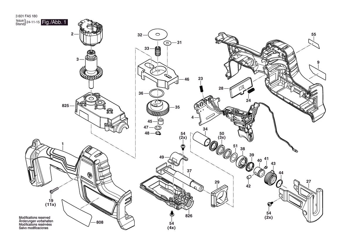
This document serves as the official spare parts and component identification guide for the Bosch GSA 18V-24 reciprocating saw (model number 3 601 FA5 100). It provides an exploded view of the tool's internal structure, which is essential for identifying parts during maintenance or repair procedures.
Device components
The provided diagram illustrates the assembly of the GSA 18V-24, including the motor housing, gear assembly, trigger mechanism, and reciprocating shaft components. Each part is numbered to correspond with official Bosch spare parts catalogs. Users should refer to this diagram when disassembling the tool to ensure correct reassembly of internal gears, bearings, and housing screws.
Maintenance and repair
The diagram highlights the internal layout of the tool. When performing maintenance, ensure the battery is removed before opening the housing. The assembly includes various screws (marked as 19 and 54) that secure the housing and internal components. Always use genuine Bosch replacement parts to maintain the safety and performance of the tool.
Contact information
For further technical support or to order spare parts, you can contact the service center: Robert Bosch d.o.o, Kneza Branimira 22, 10 040 Zagreb, Croatia. Additional information is available at https://www.boschtoolservice.com.
Official resources from the manual
Manufacturer information
Bosch
Practical help
Common problems
Tool disassembly or reassembly issues
Refer to the exploded view diagram to ensure all internal components, such as bearings (38, 51) and gears (35), are correctly positioned before securing the housing with screws (19).
Before use
- Ensure the battery is disconnected before performing any inspection or maintenance.
- Verify that all housing screws (19) are tightened correctly.
- Check the reciprocating shaft (37) for any debris or damage.
Images and diagrams
- The diagram shows the internal assembly of the GSA 18V-24.
- Numbered parts correspond to the official Bosch spare parts list.
- The exploded view helps in identifying the sequence of internal components like the motor (2, 3) and gear box (825).
Model compatibility
- This document is specific to the Bosch GSA 18V-24 model with the identification number 3 601 FA5 100.

Manual page author
Emily Carter
User documentation editor
Prepares concise manual descriptions and highlights the most useful setup, operation, and maintenance information for readers.