Tools / Power Tools
Bosch GST 12V-70 Jigsaw Exploded View Diagram
Detailed exploded view diagram for the Bosch GST 12V-70 jigsaw, identifying internal components, motor assembly, housing, and base plate parts for maintenance and repair reference.
Table of contents
Important information from the manual
This document provides an official exploded view diagram for the Bosch GST 12V-70 jigsaw. It is intended for service personnel and users performing maintenance or repairs. The diagram illustrates the internal structure, including the motor assembly, housing, base plate, and various mechanical components, allowing for precise identification of parts during disassembly and reassembly.
Component Identification
The diagram displays the following key assemblies and parts:
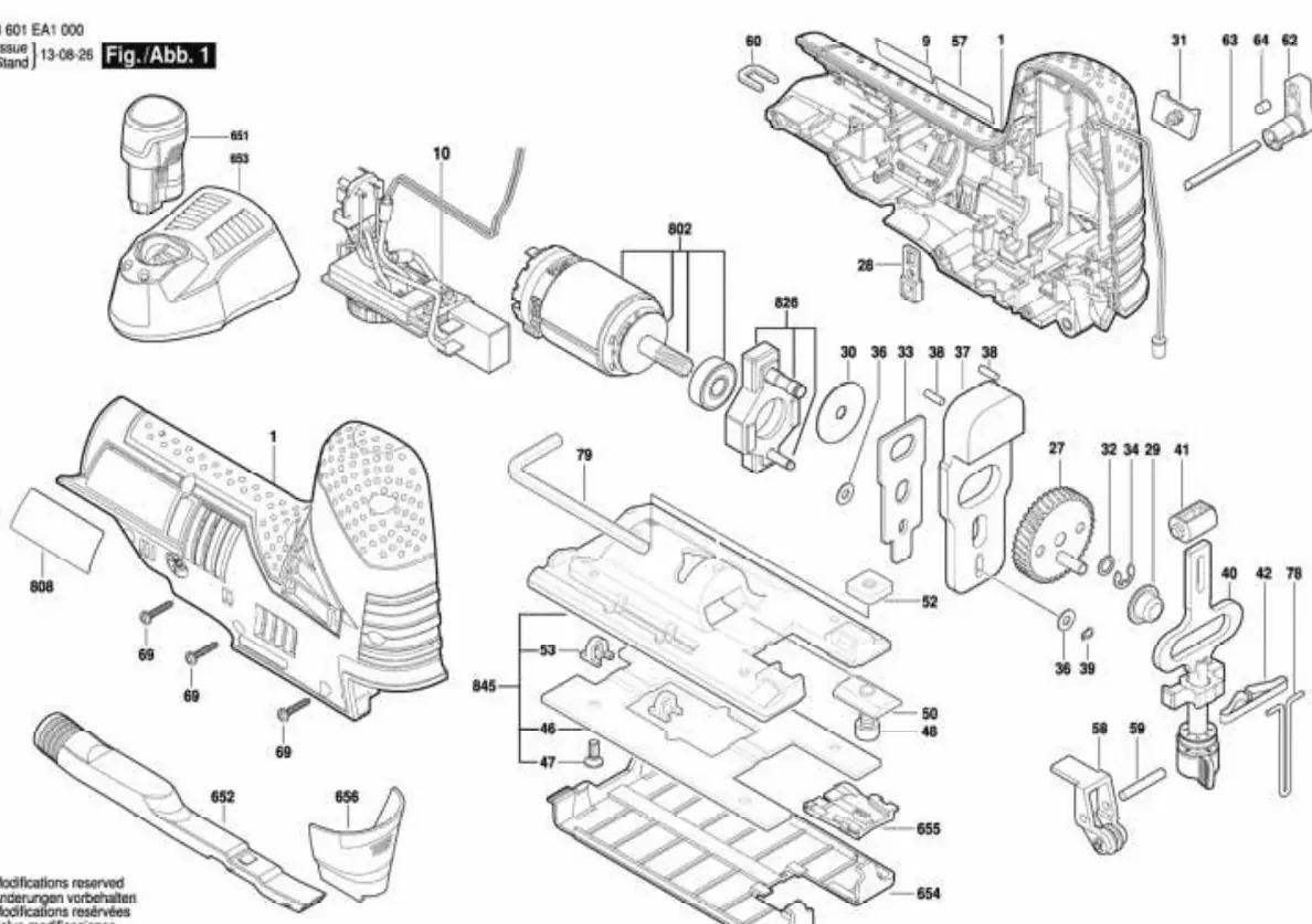
- Housing and Exterior: Main housing shells (1), base plate assembly (845), and associated fasteners (69).
- Motor Assembly: Motor unit (802) and transmission components.
- Internal Mechanism: Drive gears (27), reciprocating components, and various washers, pins, and clips (30, 32, 33, 34, 36, 37, 38, 39).
- Base and Accessories: Base plate (845), guide components (654, 655), and dust extraction accessories (652).
Maintenance and Repair
When using this diagram for repairs, ensure the tool is disconnected from the power source (battery removed). Use the numbered references to identify specific parts when ordering replacements or performing service. Ensure all washers, clips, and pins are returned to their original positions to maintain the tool's structural integrity and safety.
Manufacturer information
Bosch
Practical help
Common problems
Difficulty in identifying small internal parts during repair
Use the exploded view diagram to match the part number with the specific assembly location.
Base plate misalignment
Check the assembly of the base plate (845) and associated guide components (654, 655) against the diagram to ensure correct seating.
Before use
- Ensure the battery is removed before attempting any disassembly.
- Verify that you have the correct replacement parts corresponding to the diagram numbers.
- Organize small components (washers, clips, pins) during removal to prevent loss.
Images and diagrams
- The diagram shows the jigsaw in an exploded state, separating the housing, motor, and mechanical drive train.
- Numbered labels correspond to specific Bosch part numbers for ordering replacements.
- The base plate assembly (845) is shown as a sub-assembly for easier identification of its individual components.

Manual page author
Michael Turner
Technical manual editor
Reviews PDF manuals for structure, safety notes, and practical product details so readers can find the right information quickly.