Automotive / Lighting Accessories
Installation Instructions for Builtbright Work Bar Strobe 4
Quick guide for the Builtbright Work Bar Strobe 4 (BB6010A). Includes wiring diagrams, installation steps, flash pattern selection, and technical specifications.
Table of contents
Manual images
Click an image to enlargeQuick guide from the manual
This document provides installation and wiring instructions for the Builtbright Work Bar Strobe 4 (Model BB6010A). The device is designed for 12-24VDC systems and features multiple flash patterns and synchronization capabilities.
Specifications
- Input Voltage: 12-24VDC
- Operating Current: 0.84A @ 12VDC
- Operating Temperature: -40 to 149°F (-40 to 65°C)
Included items
- 1x LED light bar
- 1x Mounting Bezel
- 1x 3M VHB tape
- 1x Mounting Gasket
- Mounting hardware
Installation
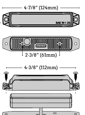
- Mount the unit to a flat surface or one with minimal curvature.
- Use the gasket or VHB tape as a template to mark drill hole locations on the mounting surface.
- Drill a 9/16 inch (14mm) hole for the wires protruding from the rear of the unit at the correct location. Deburr any sharp edges from this hole.
- Mount the light along with the mounting gasket and use the provided self-tapping screws to secure it.
Wiring
Connect the wires according to the following color codes:
- Black: To chassis ground
- White: To +VDC and memory function 1 (fuse @ 2A)
- Gray: To +VDC and memory function 2 (fuse @ 2A)
- Red: To +VDC and memory function 3 (fuse @ 2A)
- Yellow: Pattern selection
Pattern selection and synchronization
To change flash patterns, apply the YELLOW wire to +VDC:
- Next pattern: Less than 1 second
- Previous pattern: 2-4 seconds
- Steady burn: 7+ seconds
Synchronization: After setting each light to the desired pattern, connect the yellow wires of all light heads together. Up to 8 units can be synchronized.
Phase Operation: Phase 1 flashes simultaneously with Phase 1; Phase 2 flashes simultaneously with Phase 2; Phase 1 alternates with Phase 2.
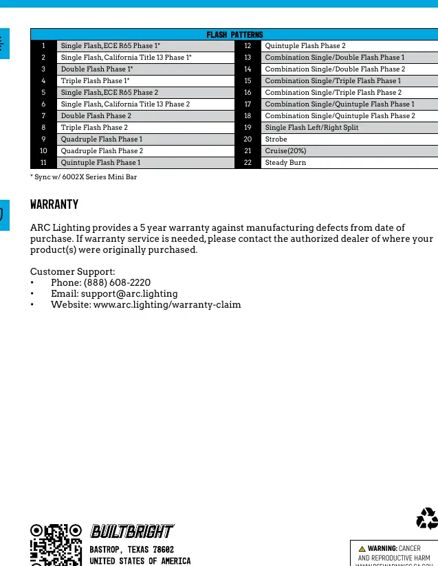
Flash patterns
The device supports 22 distinct flash patterns, including single, double, triple, quadruple, and quintuple flashes, as well as combination patterns, strobe, cruise (20%), and steady burn.
Warranty and support
ARC Lighting provides a 5-year warranty against manufacturing defects. For support, contact:
- Phone: (888) 608-2220
- Email: [email protected]
- Website: www.arc.lighting/warranty-claim
Official resources from the manual
Practical help
Common problems
Light not flashing correctly
Ensure the yellow wire is connected correctly for pattern selection and that all units are synchronized if using multiple lights.
Wiring issues
Ensure fuses are used on White, Gray, and Red wires (2A fuse recommended) to protect the circuits.
Before use
- Verify input voltage is 12-24VDC
- Ensure mounting surface is flat or has minimal curvature
- Check that you have the mounting gasket and hardware
- Deburr the 9/16 inch (14mm) hole after drilling
Specs in practice
- Input Voltage
- 12-24VDC
- Operating Current
- 0.84A at 12VDC
- Operating Temperature
- -40 to 149°F (-40 to 65°C)
Images and diagrams
- Wiring diagram shows connections for Black (ground), White/Gray/Red (+VDC), and Yellow (pattern selection).
- Installation diagram shows mounting dimensions and gasket placement.
Model compatibility
- Syncs with 6002X Series Mini Bar
- Up to 8 units can be synchronized

Manual page author
Emily Carter
User documentation editor
Prepares concise manual descriptions and highlights the most useful setup, operation, and maintenance information for readers.