Home Appliances / Refrigerators
Cell2 6-LED Narrow Profile Lighthead Installation Guide
Installation and operation guide for the Cell2 6-LED Narrow Profile Lighthead. Includes wiring instructions, flash pattern configuration, grouping modes, and mounting options for universal and L-brackets.
Table of contents
Manual images
Click an image to enlargeQuick guide from the manual
The Cell2 6-LED Narrow Profile Lighthead is designed for vehicle warning applications. Key operations include:
- Wiring: Connect Red to +VDC (with a 2A fuse), Black to Ground, and Yellow for synchronization.
- Grouping: Apply +VDC to Red and Yellow wires simultaneously to enter Grouping mode.
- Flash Patterns: Momentarily apply +VDC to the Yellow wire to cycle through 23 available patterns.
- Reset: Quickly apply +VDC to the Yellow wire three times to reset to Flash Pattern #1.
Wiring and operation
Proper wiring is essential for correct operation and synchronization of multiple lightheads.
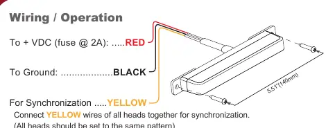
- Red Wire: Connect to +VDC. A 2A fuse is required.
- Black Wire: Connect to Ground.
- Yellow Wire: Used for synchronization and pattern selection. Connect the Yellow wires of all heads together to synchronize them. Ensure all heads are set to the same pattern.
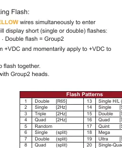
Grouping mode
Grouping allows heads to flash simultaneously or alternately.
- Apply +VDC to Red and Yellow wires simultaneously to enter Grouping mode. The lighthead will display short flashes: Single flash indicates Group 1, Double flash indicates Group 2.
- Remove the Yellow wire from +VDC and momentarily apply it to +VDC to change groups.
- Heads in the same group flash together; Group 1 heads alternate with Group 2 heads.
Flash patterns
The device features 23 distinct flash patterns. To change the pattern, momentarily apply +VDC to the Yellow wire. The unit will advance to the next pattern. To reset to the factory default (FP#1), apply +VDC to the Yellow wire three times quickly.
Installation
The lighthead supports two mounting methods depending on the bracket purchased:
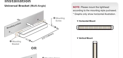
- Universal Bracket (Multi-Angle): Allows for flexible positioning. Secure the bracket to the mounting surface and attach the lighthead using the provided mounting screws.
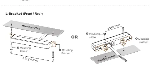
- L-Bracket (Front/Rear): Designed for specific front or rear mounting orientations.
Note: Please mount the lighthead according to the specific mounting style purchased. Graphs in the manual illustrate horizontal mounting, but vertical mounting is also supported.
Manufacturer information
Cell2
Practical help
Common problems
Lightheads are not flashing in sync
Ensure all Yellow wires are connected together and all units are set to the same flash pattern.
Need to reset to the default flash pattern
Momentarily apply +VDC to the Yellow wire three times quickly to reset to FP#1.
Lightheads are flashing alternately instead of simultaneously
Check the Grouping mode. Ensure all heads are set to the same Group (Group 1 or Group 2) to flash together.
Before use
- Verify the power source is 12-24VDC.
- Ensure a 2A fuse is installed on the Red (+VDC) wire.
- Identify the mounting bracket type (Universal or L-Bracket).
- Check the lighthead orientation before mounting, especially for FP#22.
- Confirm all wiring connections are secure and insulated.
Specs in practice
- Split Pattern
- Indicates the lighthead flashes alternating between the left and right sides.
Images and diagrams
- Wiring diagram shows the connection of Red, Black, and Yellow wires.
- Universal Bracket diagram illustrates the multi-angle mounting process.
- L-Bracket diagram shows front/rear mounting configurations.
- Mounting orientation diagrams show both horizontal and vertical installation options.
Model compatibility
- Synchronization requires connecting Yellow wires of all units.
- Some patterns are specific to SAE or R65 standards.
- Mounting hardware varies by the specific bracket purchased.

Manual page author
Michael Turner
Technical manual editor
Reviews PDF manuals for structure, safety notes, and practical product details so readers can find the right information quickly.