Furniture / Home Furnishing
Assembly Guide for Canopia Roma 12x14 Gazebo
Quick assembly guide for the Canopia Roma 12x14 gazebo, including site preparation, foundation types, tools required, and step-by-step assembly instructions.
Table of contents
Manual images
Jump to the sectionQuick guide from the manual
This document provides assembly instructions for the Canopia Roma 12x14 gazebo. It is essential to read the entire manual before starting. The assembly is a multi-part process that requires at least two people and should take approximately half a day. Ensure you have sufficient space for roof panel insertion.

Site preparation and foundation
The gazebo must be installed on a flat, level surface and anchored directly to a solid foundation. The provided screws and masonry anchors are suitable for concrete only. For other surfaces, consult an expert for appropriate fasteners. If digging holes for concrete foundations, check local requirements for depth, especially in frozen areas.
Tools and equipment
You will need the following tools: electric drill with a 10mm (3/8") bit, spirit level, Phillips head screwdriver, ladder, and a wrench (10mm, 13mm, 14mm). A cordless drill with a Phillips head is also recommended.
Safety advice
- Always wear work gloves, safety goggles, and sturdy shoes during assembly.
- Do not attempt to assemble in windy or wet conditions.
- Do not climb or stand on the roof.
- Keep children and pets away from the assembly area.
- Ensure there are no hidden pipes or cables in the ground before anchoring.
- Heavy snow must be removed from the roof if it accumulates.
Care and maintenance
Clean the product using a soft cloth and cold, clean water. Do not use acetone, abrasive cleaners, or other special detergents on the panels. Clean the product immediately after assembly is complete.
Important assembly tips


- Use a soft surface (like cardboard) under parts during assembly to prevent scratches.
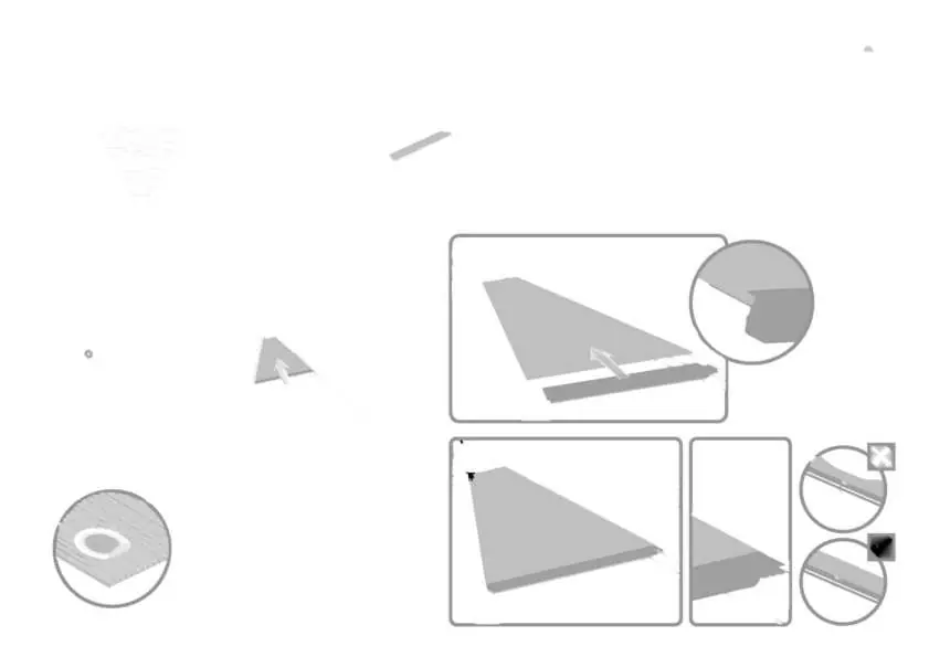
- Use silicone lubricant spray on the frame to help slide panels into profiles; do not spray the panels themselves.
- Ensure all panels stamped "THIS SIDE OUT" are facing outward for UV protection.
- Remove the protective plastic film from both sides of the panels.
- Tighten all screws only after the assembly is completed, unless temporary tightening is required to prevent profiles from sliding.
Manufacturer information
Palram Canopia
Practical help
Common problems
Difficulty sliding panels into profiles
Use a silicone lubricant spray on the frame profiles. Do not spray the panels.
Missing or damaged parts
Sort all components and check against the parts list before starting. Keep small parts in a bowl to avoid losing them.
Difficulty with screw tightening
Some screws may need temporary tightening to hold profiles in place, but fully tighten all screws only after the assembly is finished.
Before use
- Select a sunny site away from overhanging trees.
- Ensure the ground is flat, level, and solid.
- Gather all required tools (drill, level, screwdriver, ladder, wrench).
- Have at least two people available for assembly.
- Check for any local building permits or restrictions.
- Clear the site and level the ground.
Specs in practice
- Center-to-center distance
- The measurement between the centers of the support poles, crucial for foundation layout.
- THIS SIDE OUT
- Indicates the side of the panel that must face outward to provide full UV protection.
Images and diagrams
- Icons indicate whether the installer should be inside or outside the product.
- Dashed lines in diagrams refer to optional extensions only.
- Icons show when temporary screw tightening is needed versus final tightening.
Model compatibility
- Supplied screws and anchors are for concrete only.
- Consult an expert for fasteners suitable for wooden or other surface types.
- Steps marked with dashed outlines are for extension kits and may be irrelevant for a single unit.

Manual page author
David Miller
Documentation analyst
Organizes user manual content into clear summaries, with attention to model details, product context, and everyday usability.