Automotive / Lighting Accessories
User Manual for Cell2 MINI-FALCON Minibar
Quick guide for the Cell2 MINI-FALCON minibar. Learn about wiring, flash pattern selection, and installation methods for 1-bolt, 2-bolt, and magnetic mounts.
Table of contents
Manual images
Click an image to enlargeQuick guide from the manual
This document provides essential wiring, operation, and installation instructions for the Cell2 MINI-FALCON minibar. Users should note that ECE R65 compliance requires the use of flash pattern 1 (Double), and activating the dim function will invalidate this approval.
Wiring and Operation
The unit uses a 4-wire cable system for hardwired installations:
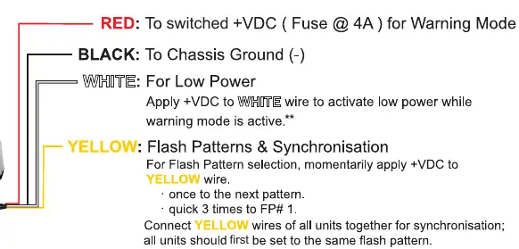
- Red: Connect to switched +VDC (use a 4A fuse) for Warning Mode.
- Black: Connect to Chassis Ground (-).
- White: Apply +VDC to activate low power mode while warning mode is active.
- Yellow: Used for flash pattern selection and synchronization. Momentarily apply +VDC to change patterns or connect yellow wires of multiple units together to synchronize them.
For models with a 2-Button Cigar Plug, use the ON/OFF switch to activate the warning mode and the Flash Pattern switch to cycle through patterns.
Flash Patterns
The device supports 29 different flash patterns. To select a pattern, momentarily press the Flash Pattern switch or apply +VDC to the yellow wire. To reset to pattern 1, quickly trigger the pattern selection 3 times.
Installation
The installation method depends on the specific mounting kit included with your model:
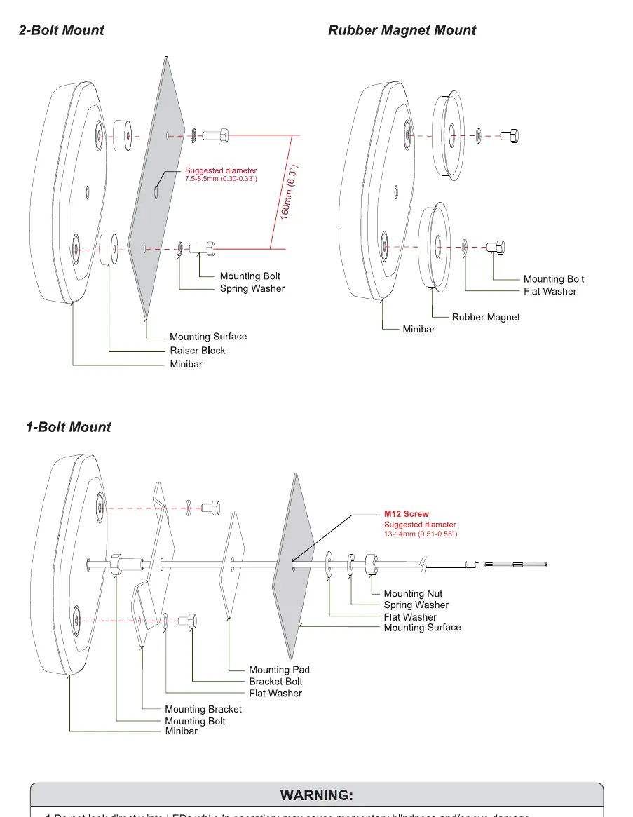
- 1-Bolt Mount: Requires a mounting bracket, pad, and M12 screw. Ensure the mounting surface hole diameter is 13-14mm.
- 2-Bolt Mount: Uses a raiser block, mounting bolts, and spring washers. Ensure the mounting surface hole diameter is 7.5-8.5mm.
- Rubber Magnet Mount: Uses a rubber magnet, flat washers, and mounting bolts.
Safety Warnings
- Do not look directly into the LEDs while in operation, as this may cause momentary blindness or eye damage.
- The use of any magnetically mounted warning device on the outside of a vehicle in motion is not recommended and is at the sole risk and responsibility of the user.
Manufacturer information
Cell2
Practical help
Common problems
Device not flashing correctly or out of sync
Ensure all units are connected via the yellow wire and set to the same flash pattern.
Low power mode not activating
Ensure +VDC is applied to the white wire while the main warning mode is active.
Flash pattern needs to be reset
Quickly trigger the pattern selection (via switch or yellow wire) 3 times to reset to pattern 1.
Before use
- Verify the fuse rating is 4A for the red wire connection.
- Ensure all units are set to the same flash pattern if synchronizing multiple units.
- Check that the mounting surface hole diameter matches the requirements for your specific mount (7.5-8.5mm for 2-bolt, 13-14mm for 1-bolt).
- Confirm the vehicle is stationary if using the magnetic mount.
Model compatibility
- ECE R65 compliance requires using flash pattern 1 (Double).
- Activating the dim function invalidates R65 approval.

Manual page author
David Miller
Documentation analyst
Organizes user manual content into clear summaries, with attention to model details, product context, and everyday usability.