Industrial / Door Operators
User Manual for CO-Z 1400LBS Automatic Sliding Gate Opener
Comprehensive user manual for the CO-Z 1400LBS (600KG) Automatic Sliding Gate Opener. Includes installation instructions, wiring diagrams, remote control pairing, and troubleshooting steps.
Table of contents
Manual images
Click an image to enlargeQuick guide from the manual
This manual provides instructions for the CO-Z 1400LBS (600KG) Automatic Sliding Gate Opener. Before installation, ensure the gate moves smoothly by hand and that the power supply matches the 110V/60Hz requirement. Installation must be performed by professionals. The system supports up to 20 remote controls and includes auto-close functionality.
Installation Procedures
Preparation: Ensure the gate rail is horizontal and the gate glides smoothly. Bury power and control cables in separate PVC tubes to protect them.
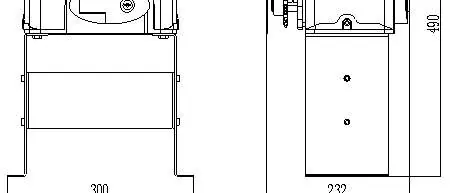
Concrete Pedestal: Cast a concrete pedestal (19.69" x 13.78" x 7.87") to firmly mount the opener. Verify the distance between the gate and the opener before casting.
Main Engine Installation: Dismantle the plastic housing, assemble the mounting base, and secure the engine to the base using the provided screws and washers. Unlock the engine using the manual release key to rotate the output sprocket during installation.
Chain Installation: Connect the tie rod to the chain and fasten it to the door connecting plate. Ensure the distance between the main engine and chain ends is at least 30cm (11.81 inches).
Limit Switch Adjustment
Use the manual release key to move the gate to the desired open/close positions. Fix the magnetic limit switch blocks on the rail. After power-on, test the gate and adjust the position of the magnetic blocks until the gate stops at the correct locations.
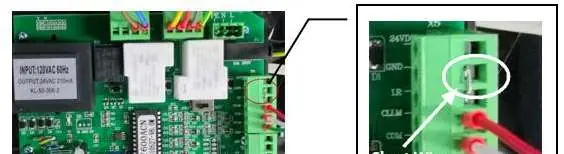
Control Board and Wiring
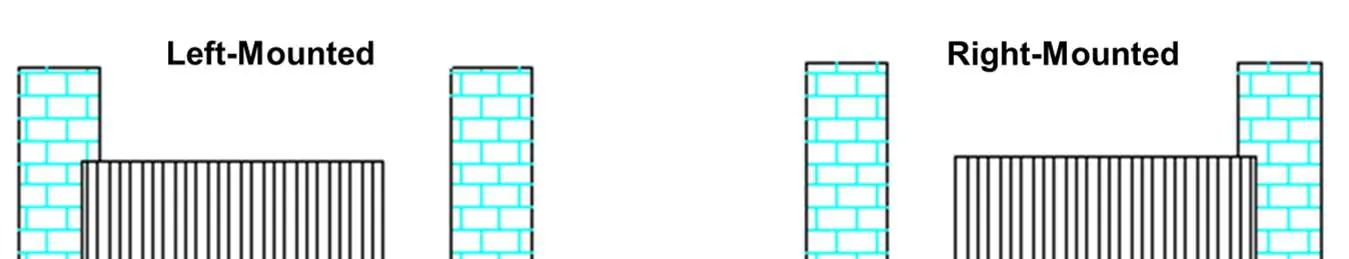
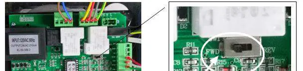
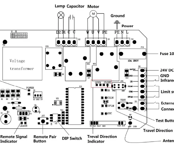
The control board features terminals for power (X4: PE, N, L), alarm lamps (X2: D1, D2), external buttons (X5: COM, OSC), and photocell sensors (X6: 24VDC, GND, I.R). Ensure the Travel Direction Switch is set to FWD for right-mounted gates or REV for left-mounted gates.
Remote Control and Settings
Pairing: Press the Remote Pair Button (AN1) on the control board, then press the button on the remote control. The indicator will flash and then go off once paired.
DIP Switches: Use the DIP switches to configure external button modes and auto-close time settings (15, 30, 45 seconds, or disabled).
Troubleshooting
If the gate fails to operate, check the power supply, fuse (code FU), and wiring. If the gate opens but won't close, check the photocell wiring and alignment. If the remote control fails, check the battery and re-perform the pairing process.
Practical help
Common problems
Gate does not open or close, LED is off
Check power supply, replace burnt fuse (code FU), or check control board wiring.
Gate opens but will not close
Check photocell wiring/alignment, remove obstructions, or reduce obstacle sensitivity.
Remote control does not work
Replace remote battery or re-conduct the remote control learning process.
Motor has noise but gate does not move
Check capacitor, verify capacitor wiring, or adjust gate/motor alignment.
Gate does not stop at limit position
Check limit switch wiring and adjust the position/height of the magnetic limit switch blocks.
Before use
- Ensure gate glides smoothly by hand
- Verify power voltage matches 110V
- Install safety stop blocks on both ends of the rail
- Bury cables in separate PVC tubes
- Cast concrete pedestal (19.69" x 13.78" x 7.87")
- Check that the gate is horizontal
Specs in practice
- Maximum Gate Weight
- 600KG (1400Lbs)
- Power Supply
- 110V/60Hz
- Working Temperature
- -20°C to +70°C
Images and diagrams
- Wiring diagram for control board connections
- Chain and tie rod installation assembly
- Magnetic limit switch block positioning
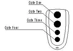
- Remote control button layout
- Left vs Right mounting orientation
Model compatibility
- Compatible with 433.92 MHz remote controls
- Requires 1.5mm² power cable
- Must be installed inside an enclosure or yard

Manual page author
Michael Turner
Technical manual editor
Reviews PDF manuals for structure, safety notes, and practical product details so readers can find the right information quickly.