Industrial / Vehicle Barriers
DoorKing Standard Arm Bracket Hardware Kits
Installation guide for DoorKing standard arm bracket hardware kits, covering wiring, power supply mounting, and arm assembly for 1601, 1602, and 1603 barrier gate operators.
Table of contents
Manual images
Click an image to enlargeQuick Installation Guide
This manual provides installation instructions for various DoorKing hardware kits designed for 1600 series barrier gate operators. Before beginning, ensure you have the correct kit for your operator model. Always turn off all power to the operator before performing any installation or wiring.
- Standard Arm Bracket: Must be installed on the operator hub before attaching the arm.
- Wiring: Ensure at least 13 inches of slack in the wire harness between cable grips to allow for arm rotation.
- Compatibility: Verify if your kit is compatible with your specific operator (1601, 1602, or 1603) and arm type (14ft or 17ft).
Standard Arm Bracket Installation
The standard arm bracket is the foundation for the gate arm. The operator hub must already be installed on the operator. The hub can be mounted on either side of the operator.
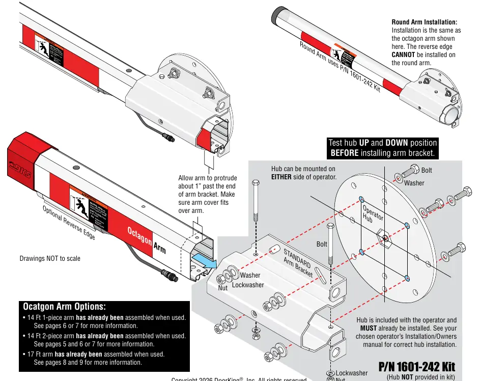
- Ensure the operator hub is installed according to the operator's specific owner's manual.
- Attach the standard arm bracket to the operator hub using the provided bolts, washers, lockwashers, and nuts.
- Test the hub in both UP and DOWN positions before installing the arm bracket.
Wiring and Power Supply
Proper wiring is critical for the operation of the arm and safety accessories like the reverse edge.
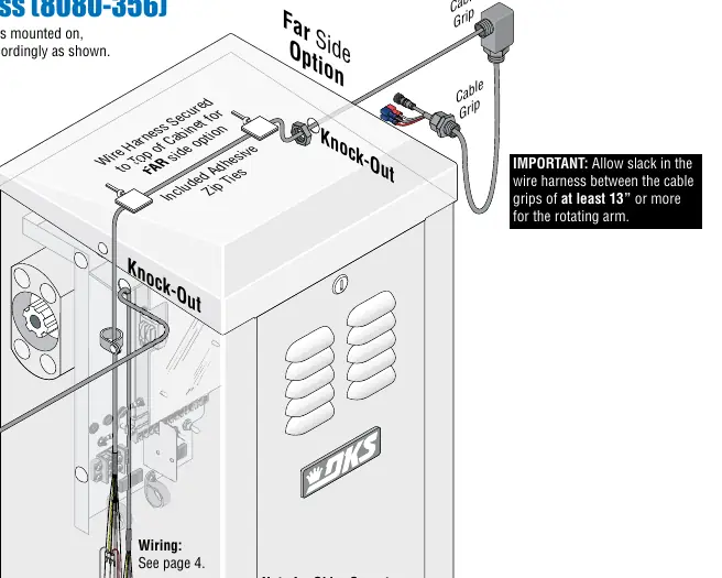
- Wire Harness: Route the wire harness through the operator cabinet. Remove the knock-out and secure the harness. Use adhesive zip ties to secure the harness to the bottom of the arm bracket.
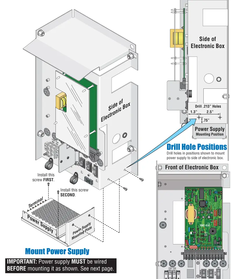
- Power Supply: If required by your kit, mount the power supply to the side of the electronic box. Drill holes as specified in the manual (.213" holes) and secure the mounting plate. The power supply must be wired before mounting.
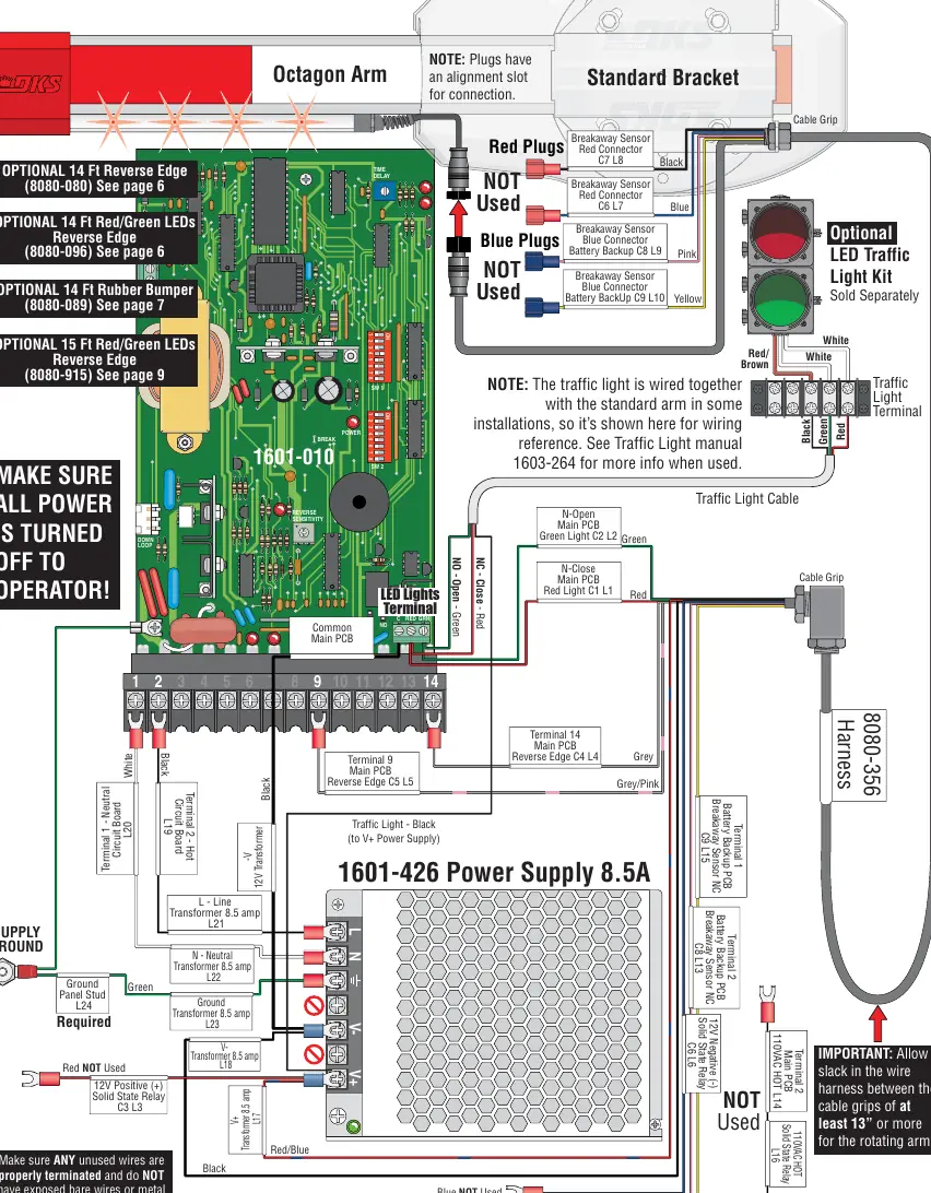
- Connections: Refer to the wiring diagram on page 4 for specific terminal connections. Ensure all unused wires are properly terminated to prevent malfunctions.
Arm Assembly and Accessories
The manual covers assembly for different arm configurations:
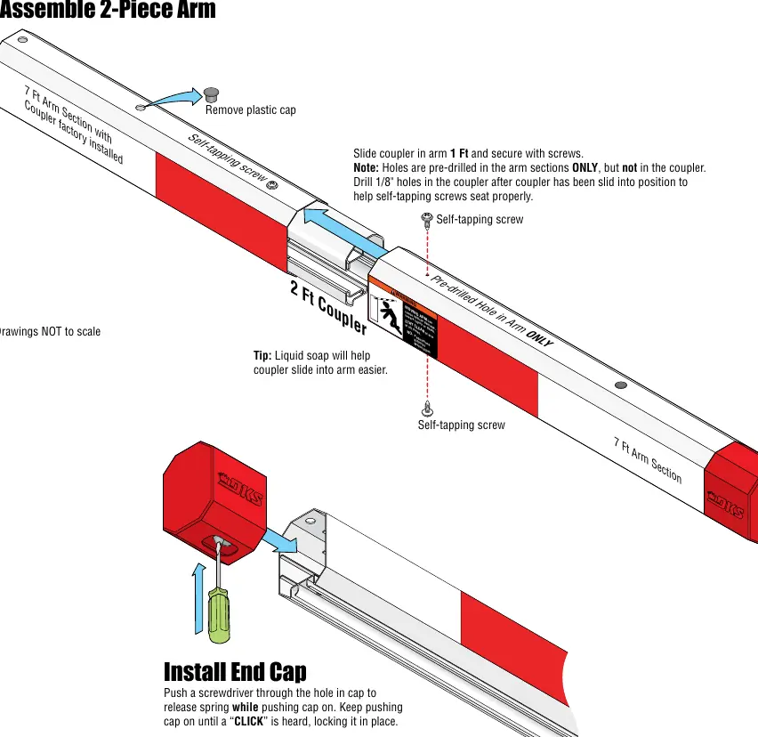
- 14 Ft 2-Piece Arm: Assemble the two 7ft sections using the 2ft coupler. Secure with self-tapping screws. Drill 1/8" holes in the coupler after sliding it into position.
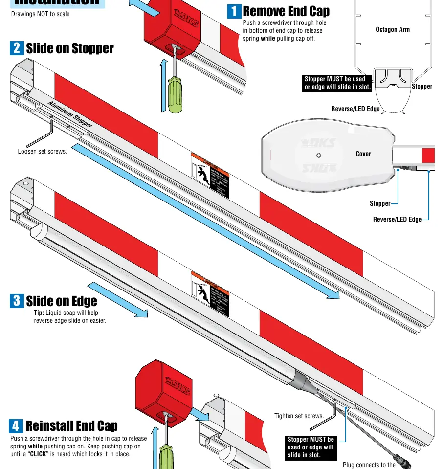
- Reverse Edge/LED Installation: Remove the end cap, slide on the stopper, and then slide the reverse edge onto the arm. Reinstall the end cap until it clicks.
- Rubber Bumper: Slide the rubber bumper onto the arm, ensuring the 3" trim end is on the operator side.
- 17 Ft Arm (1602 Only): Uses a 3ft extension. Follow the specific assembly instructions for the 1ft and 2ft couplers to ensure stiffness.
Modifications
If using an older existing arm cover, you may need to cut a notch to accommodate the reverse edge. Use the template provided on page 10 as a guide for removing material.
Practical help
Common problems
Arm cover interference
If using an older existing arm cover, you must cut a notch for the reverse edge using the template provided in the manual.
Reverse edge malfunction
Ensure the stopper is properly installed and tightened so the edge does not slide in the slot. Do not operate the arm with a malfunctioning reverse edge.
Wire harness binding
Ensure there is at least 13 inches of slack in the wire harness between the cable grips to allow for the arm's rotation.
Before use
- Turn off all power to the operator.
- Verify the kit is compatible with your operator model (1601, 1602, or 1603).
- Ensure the operator hub is installed and tested in both UP and DOWN positions.
- Check that all unused wires are properly terminated.
- Ensure the stopper is in position when installing a reverse edge.
Images and diagrams
- Page 1 shows the standard arm bracket installation on the operator hub.
- Page 4 provides a detailed wiring diagram for the octagon arm and power supply.
- Page 5 illustrates the assembly of the 2-piece arm using couplers and self-tapping screws.
Model compatibility
- 17 Ft Octagon Arm assembly is for 1602 barrier gate operators ONLY.
- Reverse edge cannot be installed on round arms.
- 14 Ft Reverse Edge kits cannot be used with 1602 operators.

Manual page author
David Miller
Documentation analyst
Organizes user manual content into clear summaries, with attention to model details, product context, and everyday usability.