Furniture / Tables & Desks
Assembly Instructions for Dams Connex 1600mm Outer Leg Frame
Step-by-step assembly guide for the Dams Connex 1600mm Outer Leg Frame (COU1600OL). Includes component checklists, hardware requirements, and detailed installation procedures for frame construction and desktop attachment.
Table of contents
Manual images
Click an image to enlargeQuick guide from the manual
This document provides assembly instructions for the Dams Connex 1600mm Outer Leg Frame. Before beginning, ensure you have a 4mm Allen key. Always use a 2-man lift when handling heavy items and keep all fittings away from children. If you are assembling a larger configuration or adding cable management, refer to the specific intermediate leg frame or cable tray instructions before proceeding.
Components and Fittings
Before starting assembly, verify that you have all required parts:
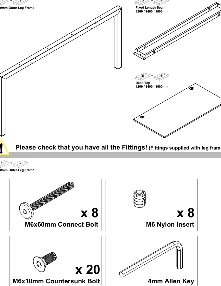
- Components: 1600mm Outer Leg Frame, Fixed Length Beam (1200/1400/1600mm), and Desk Top (1200/1400/1600mm).
- Fittings: 8x M6x60mm Connect Bolts, 8x M6 Nylon Inserts, 20x M6x10mm Countersunk Bolts, and a 4mm Allen Key.
Assembly Steps
Frame Construction
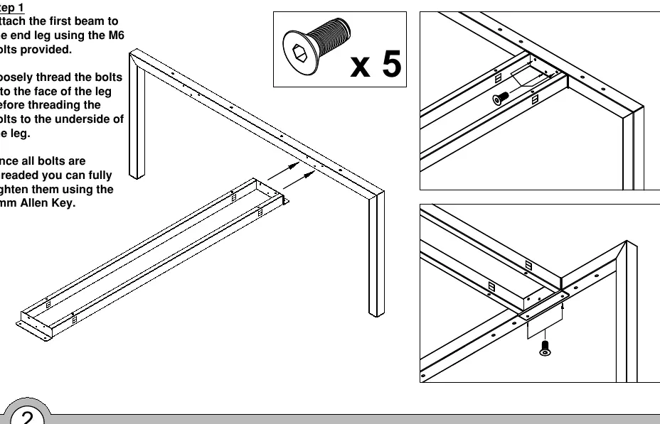
- Step 1: Attach the first beam to the end leg using the provided M6 bolts. Loosely thread the bolts into the face of the leg before threading them into the underside. Fully tighten once all are threaded.
- Step 2: Attach the second beam to the end leg using the same method.
- Step 3: Attach the remaining outer leg frame to the beams using the same method as before.
Desktop Installation
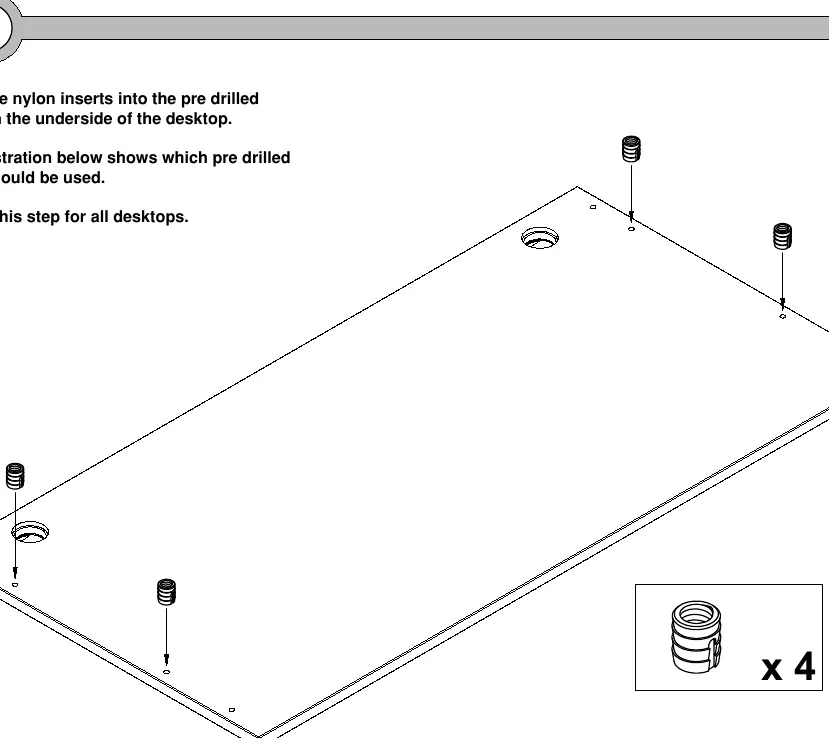
- Step 4: Insert the nylon inserts into the pre-drilled holes on the underside of the desktop. Repeat for all desktops.
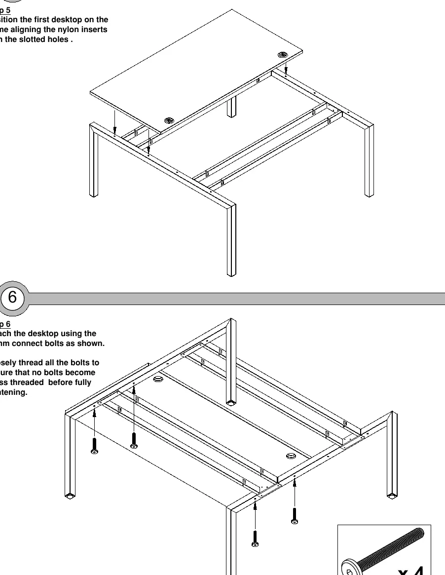
- Step 5: Position the first desktop on the frame, aligning the nylon inserts with the slotted holes.
- Step 6: Attach the desktop using the 60mm connect bolts. Loosely thread all bolts first to ensure they do not become cross-threaded before fully tightening.
- Step 7: Position the remaining desktop on the frame, aligning the nylon inserts with the slotted holes.
- Step 8: Attach the remaining desktop using the 60mm connect bolts, ensuring all are loosely threaded before final tightening.
Practical help
Common problems
Bolts becoming cross-threaded
Loosely thread all bolts into position before fully tightening them with the Allen key.
Heavy lifting
Use a 2-man lift to move and position the desk components to avoid injury.
Before use
- Verify all components are present (Leg frames, beams, desktops).
- Verify all fittings are present (M6x60mm bolts, M6 nylon inserts, M6x10mm bolts).
- Ensure you have a 4mm Allen key.
- Check if you need to install cable management trays before attaching the desktop.
Specs in practice
- M6x60mm Connect Bolt
- Used for securing the desktop to the frame structure.
- M6x10mm Countersunk Bolt
- Used for securing the beams to the leg frames.
- M6 Nylon Insert
- Plastic inserts placed into the desktop to receive the connect bolts.
Images and diagrams
- Steps 1-3 illustrate the assembly of the metal frame structure.
- Steps 4-8 illustrate the preparation and attachment of the desktop surfaces to the frame.
Model compatibility
- If assembling as part of a larger configuration, refer to intermediate leg frame instructions first.
- If adding horizontal cable management, refer to drop-down cable tray instructions before attaching desktops.

Manual page author
Emily Carter
User documentation editor
Prepares concise manual descriptions and highlights the most useful setup, operation, and maintenance information for readers.