Industrial / Sensor Accessories
Inductive Proximity Sensor di-soric DCC 12 M 04B POLK Datasheet
Quick guide and technical specifications for the di-soric DCC 12 M 04B POLK inductive proximity sensor. Includes wiring diagrams, installation requirements, and operating parameters.
Table of contents
Quick guide from the manual
The di-soric DCC 12 M 04B POLK is an inductive proximity sensor designed for digital evaluation. This document provides the essential technical specifications and wiring requirements for proper installation and operation. Ensure the power supply is within the 10-30 V DC range and that the sensor is installed according to the flush mounting specifications.
Technical Data
The sensor operates under the following technical parameters:
- Service voltage: 10 to 30 V DC
- Switching output: PNP, 200 mA, NC (Normally Closed)
- Switching distance (SN): 4 mm
- Switching frequency: 800 Hz
- Internal power consumption: < 10 mA
- Voltage drop (max.): 2.4 V
- Standardized measuring plate: 12 x 12 x 1 mm
Installation and Environment
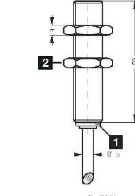
The sensor is designed for flush installation. It features a nickel-plated brass housing with a length of 50 mm and an M12 x 1 thread. The device is rated IP 67, making it suitable for harsh environments, and operates within an ambient temperature range of -25 to +70 °C.
Wiring
The sensor is connected via a 2.0 m PVC cable. The wiring configuration is as follows:
- BN (Brown): Positive (+)
- BK (Black): Signal (S)
- BU (Blue): Negative (-)
Practical help
Common problems
Sensor not switching
Verify that the power supply is within the 10-30 V DC range and check that the target object is within the 4 mm switching distance.
Incorrect output signal
Ensure the wiring matches the diagram: Brown to positive, Blue to negative, and Black to the signal input.
Before use
- Verify power supply is 10-30 V DC.
- Ensure the installation environment is within -25 to +70 °C.
- Confirm the mounting type is flush.
- Check cable integrity and connections (BN, BK, BU).
Specs in practice
- Switching output: PNP, NC
- The sensor provides a positive voltage signal when active and is Normally Closed (circuit is closed when no target is detected).
- Protection type: IP 67
- The device is dust-tight and protected against the effects of temporary immersion in water.
- Switching distance (SN): 4 mm
- The maximum distance at which the sensor reliably detects the standardized measuring plate.
Images and diagrams
- The wiring diagram shows the three-wire connection: Brown (BN) connects to positive, Blue (BU) connects to negative, and Black (BK) carries the PNP signal.
Model compatibility
- Requires a standardized measuring plate of 12 x 12 x 1 mm for optimal performance.

Manual page author
David Miller
Documentation analyst
Organizes user manual content into clear summaries, with attention to model details, product context, and everyday usability.