HVAC / Air Handlers
Installation Guide for Ecoer EAHETN Series Multi-Position Air Handler
Quick installation and setup guide for the Ecoer EAHETN Series Multi-Position Air Handler. Includes wiring diagrams, condensate drain setup, TXV coil installation, and system startup procedures.
Table of contents
Manual images
Click an image to enlargeQuick Guide from the Manual
This installation guide provides essential procedures for setting up the Ecoer EAHETN Series Multi-Position Air Handler. Key requirements include:
- Power Supply: Designed for 120V, single phase, 60Hz.
- Clearance: Ensure 2.5–3.5 feet of clearance in front for service.
- Drainage: An auxiliary drain pan is mandatory. Install a condensate trap on the primary drain line.
- Hydronic Heat: Requires connection to a water heater; ensure the system is purged of air before startup.
- Orientation: The unit supports vertical, horizontal, and counterflow configurations (requires specific kits for counterflow).
Safety Instructions
Only certified technicians or those meeting NATE requirements should perform installation. Always disconnect all power sources before servicing. The unit is not approved for outdoor installations. Ensure proper ventilation if installed in enclosed areas with carbon monoxide-producing devices.
Installation Preparation
Inspect the product for shipping damage upon receipt. Verify model numbers match your order. Ensure the unit is adequately sized; the tonnage of the outdoor unit should never exceed the tonnage of this air handler.

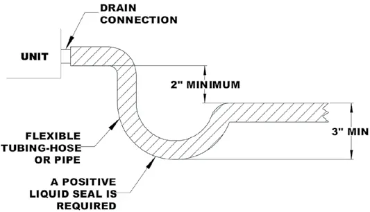
Condensate Drain
Drain lines from the auxiliary drain pan must not be connected to the primary drain line. Install drain lines with a 1/4" per foot pitch. A condensate trap must be installed on the primary drain line below the bottom of the drain pan. If the drain pan is plastic, use Teflon tape; do not use solvent-based pipe dope.
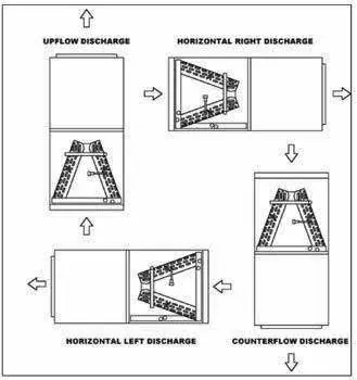
Air Handler Orientation
The unit can be installed in vertical or right horizontal positions without modifications. For counterflow applications, the horizontal drain pan must be removed. When in a horizontal orientation, an auxiliary drain pan is required.
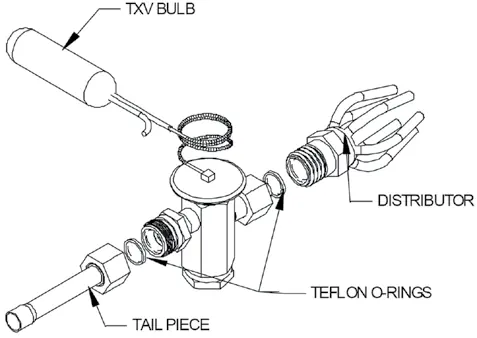
TXV Coil Installation
The TXV sensing bulb must be mounted on the suction line, approximately 6 inches from the TXV or coil housing. It must be in direct contact with the suction line, mounted horizontally at the 2 o'clock or 10 o'clock position, and insulated from outside air.
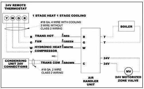
Electrical Installation
Wiring must comply with the National Electric Code. Connect power wiring to the line side connections and secure the ground wire to the grounding lug. For units with factory-installed pumps, the pump energizes on a call for heat. If using a boiler, connect wires to the "BOILER" T T terminals.
System Charging and Start-Up
Before starting the pump, the hydronic coil and all water lines must be purged of air. Ignite the water heater and set the thermostat to 140°F. Use the air bleed valve to purge air from the system. Ensure the motor is pre-loaded with the factory program.
Operation and Maintenance
Inspect and clean or replace air filters every month. Never operate the system without filters. Annual check-ups by a qualified service technician are recommended to ensure efficiency and prevent malfunction.
Troubleshooting
If the pump is noisy, the system may not be fully purged of air. If there is little or no heat, check for reversed inlet connections, incorrect water heater thermostat settings, or restrictions in the heating system.
Practical help
Common problems
Noisy Pump
System may not be fully purged of air. Purge the system again as described in the start-up section.
T&P valve on water heater weeps
Usually caused by a backflow preventer. An expansion tank may be necessary.
Hot water circulating during cooling cycle
The check valve may be stuck open. Inspect and repair.
Little or no heat from water coil
Purge the system, check for reversed inlet connections, or verify water heater thermostat calibration.
Before use
- Verify model number and options match your order.
- Ensure 120V, single phase, 60Hz power supply is available.
- Install an auxiliary drain pan under the unit.
- Install a condensate trap on the primary drain line.
- Ensure 2.5-3.5 feet of clearance in front of the unit.
- Purge all air from the hydronic coil and water lines before starting the pump.
Images and diagrams
- Fig 3A-1: Minimum clearance requirements for service access.
- Fig 4D-1: Correct condensate trap installation.
- Fig 6-1: Available air handler orientations.
- Fig 11-1: Typical electrical wiring connections.
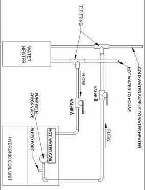
- Fig 15-1: Hydronic coil connection to water heater system.
Model compatibility
- Not approved for outdoor installations.
- Requires a downflow kit (DFK) for counter/downflow applications.
- Hydronic heat configuration is not suitable for electric heat.
- Units installed in Massachusetts must comply with CMR 248.

Manual page author
David Miller
Documentation analyst
Organizes user manual content into clear summaries, with attention to model details, product context, and everyday usability.