Electronics / Routers
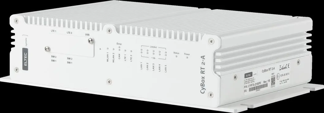
Installation Manual for Eltec CyBox RT 2-A Wireless Automotive Router
Comprehensive installation guide for the Eltec CyBox RT 2-A wireless automotive router. Includes hardware connection, mounting instructions, SIM card setup, LED status indicators, and safety guidelines.
Quick answers from the manual
Quick answer
- The CyBox RT 2-A is a wireless automotive router. It requires 12-24 V DC power, proper grounding via the M6 stud, and 150 mm of clearance for cooling. It features 5 Ethernet ports, CAN interfaces, and dual SIM slots per LTE modem. p. 3, 9, 10, 17
Key actions
- Mounting the device p. 9, 17
- Connecting the earthing cable p. 10, 18
- Installing SIM cards p. 8, 16
First start
- The device starts automatically as soon as it is supplied with power. p. 10, 18
Problems and fixes
Resetting to factory settings
Hold the reset switch for more than 5 seconds.
p. 8, 16Maintenance and reset
- Use the reset switch located beside the service cover to reset the device or clear configuration. p. 8, 16
Technical specifications
| Parameter | Value | Meaning | Pages |
|---|---|---|---|
| Input Voltage | 12-24 V DC | Nominal input voltage range. | p. 5, 13 |
| Protection Class | IP40 | Ingress protection rating. | p. 9, 17 |
Where to find it in the PDF
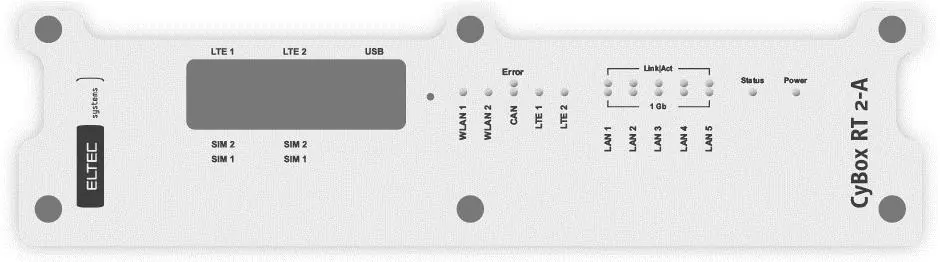
- Front Panel Overview p. 13
- Back Panel Overview p. 14
- Dimensions p. 17
Table of contents
Manual images
Click an image to enlargeQuick guide from the manual
This installation manual is intended for system developers and integrators. The CyBox RT 2-A is a wireless automotive router designed for professional use. Key safety and operational requirements include:
- Electrical Safety: The device operates on 12-24 V DC. Always connect the device to protective earth before connecting the power supply.
- Thermal Management: The device can exceed 80°C during operation. Ensure at least 150 mm of free space around the housing for heat dissipation.
- Installation Orientation: For optimal heat dissipation, mount the device with connectors facing down.
- Handling: Only qualified personnel should install or maintain the device. Always disconnect power before handling or disassembling.
Hardware overview
The device features various interfaces for connectivity:
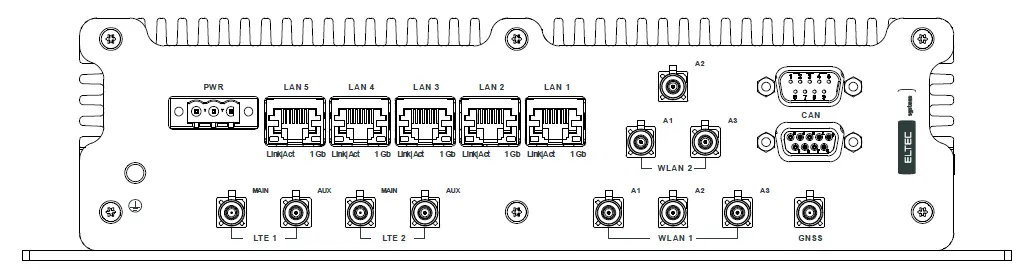
- Power Supply: Uses an MSTB 2.5/3 GF connector.
- Ethernet: Five 1 Gb Ethernet ports (RJ45).
- CAN Interfaces: Two D-Sub 9 connectors for CAN bus topology.
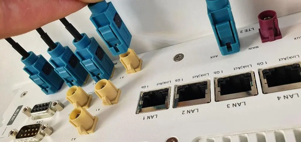
- Antennas: FAKRA connectors for LTE and GNSS antennas.
- USB: A dedicated maintenance port (USB 2.0 Type A) located behind the service cover.
Mounting and installation
The device is designed for mounting on a flat, stable surface in either horizontal or vertical orientation.
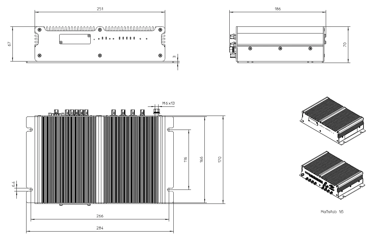
- Use the four mounting cutouts provided on the housing.
- Secure the device using M6 screws with washers.
- Earthing: A M6 earthing stud is located on the front panel. Use a cable with a cross-section of at least 2.5 mm² and a wire end sleeve. Tighten the nut to 3 Nm.
- Electrical Connection: Ensure the power supply voltage matches the device specifications. The device starts automatically upon receiving power; there is no on/off switch.
SIM card installation
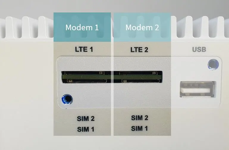
The CyBox RT 2-A supports two SIM slots per LTE modem.
- Remove the service cover using a Torx 10 screwdriver.
- Insert the SIM cards into the designated slots.
- Close the service cover and tighten the screws to a maximum torque of 0.55 Nm.
- Important: Do not change SIM cards while the device is powered. Switching between SIM slots takes approximately 30 seconds.
Reset switch
A hidden reset switch is located on the front panel, accessible via a paper clip.
- < 2 seconds: Reset after release.
- 2-5 seconds: No action.
- > 5 seconds: Remove custom configuration and reset.
LED indicators
The front panel LEDs provide status information:
- Power LED: Green (On) indicates correct input power.
- Status LED: Green (On) indicates normal operation; Red (On) indicates an error.
- Module LEDs: Indicate if WLAN, CAN, or LTE modules are configured.
- LAN LEDs: Indicate link status and activity for the Ethernet ports.
Practical help
Common problems
Device overheating
Ensure at least 150 mm of free space around the housing and mount with connectors facing down for optimal heat dissipation.
SIM card switching delay
If using only one SIM card, use slot 1 to avoid switching delays during booting.
Configuration issues
Use the reset switch (hold > 5 seconds) to clear custom configuration and reset the device.
Before use
- Verify power supply voltage is between 12 V and 24 V DC.
- Ensure the device is properly grounded via the M6 earthing stud.
- Check that all cables are intact and undamaged.
- Ensure 150 mm clearance around the device.
- Confirm antennas are connected correctly (click sound for FAKRA connectors).
Specs in practice
- Input Voltage
- 12-24 V DC (up to 32 V DC).
- Protection Class
- IP40.
- Torque (Service Cover)
- Maximum 0.55 Nm for Torx 10 screws.
- Earthing Torque
- 3 Nm for the earthing stud nut.
Images and diagrams
- Front panel: Contains SIM slots, USB port, and status LEDs.
- Back panel: Contains power, Ethernet, CAN, and antenna connectors.
- SIM slot assignment: 2 slots per modem, slot 1 is the lower one.
- Earthing: Shows the assembly order of the earthing cable on the stud.
Model compatibility
- Only qualified personnel should perform installation.
- USB port is for maintenance only; do not use while in operation.
- Device has no on/off switch.

Manual page author
Michael Turner
Technical manual editor
Reviews PDF manuals for structure, safety notes, and practical product details so readers can find the right information quickly.