Electronics / Networking
Installation Manual for Westermo CYBOX RT 2-A Automotive Wireless Router
Comprehensive installation guide for the Westermo CYBOX RT 2-A automotive wireless router. Includes mounting instructions, wiring diagrams, connector pinouts, LED status explanations, and SIM card installation procedures.
Quick answers from the manual
Quick answer
- The CYBOX RT 2-A is an automotive wireless router. Installation requires a 12-24 VDC power source, a protective earth connection, and adequate ventilation (150mm clearance). p. 1, 12, 13, 20
Key actions
- Mounting the device p. 12
- Connecting earthing cable p. 13
- Installing SIM cards p. 11
First start
- The device starts automatically when power is supplied. p. 13
Problems and fixes
Device overheating
Ensure 150mm clearance and connectors facing down.
p. 12Maintenance and reset
- Use a paper clip to press the hidden reset switch. p. 11
Technical specifications
| Parameter | Value | Meaning | Pages |
|---|---|---|---|
| Input Voltage | 12-24 VDC | Nominal input voltage range | p. 7 |
| Protection Class | IP40 | Housing protection rating | p. 12 |
Where to find it in the PDF
- Hardware Connectors p. 3, 4, 5, 6
- Mounting p. 12
Table of contents
Manual images
Click an image to enlargeQuick Guide
The Westermo CYBOX RT 2-A is an automotive wireless router designed for professional integration. Before installation, ensure the device is handled by qualified personnel only. The device operates on 12-24 VDC and requires a protective earth connection. Ensure a minimum clearance of 150 mm around the housing for heat dissipation, and mount the device with connectors facing down for optimal thermal performance.
Hardware Overview
The device features various connectors for connectivity and power:
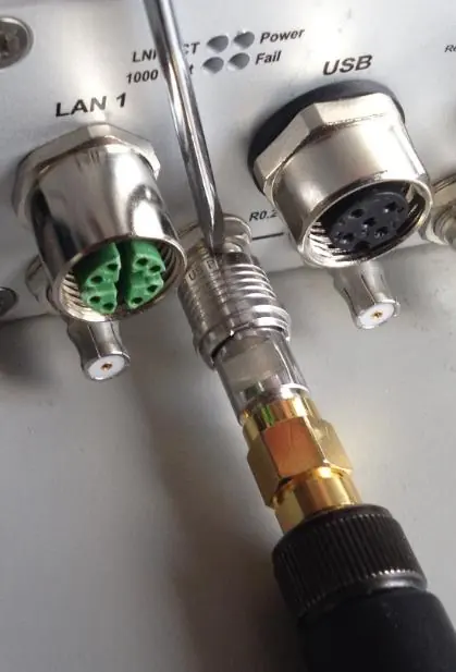
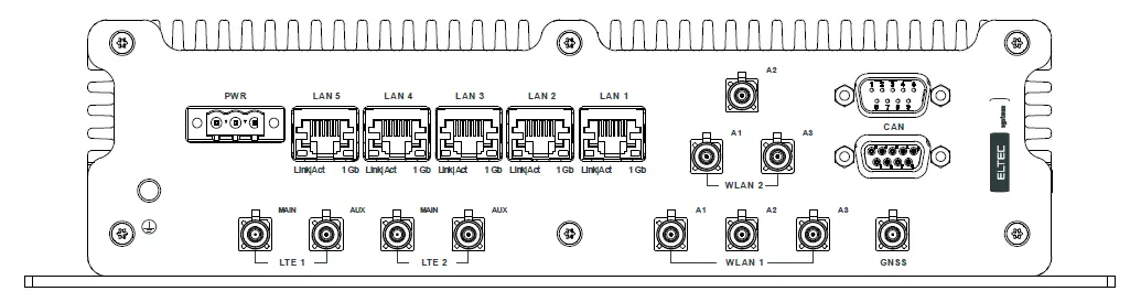
- Power Supply: Uses an MSTB 2.5/3 PCB header.
- Ethernet: Five RJ45 Gigabit ports.
- CAN Interfaces: Two D-Sub 9 connectors for bus topology.
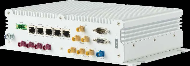
- Antennas: Supports QLS, FAKRA, and SMA/RP-SMA connectors depending on the specific model configuration.
Mounting and Installation
Follow these steps for secure installation:
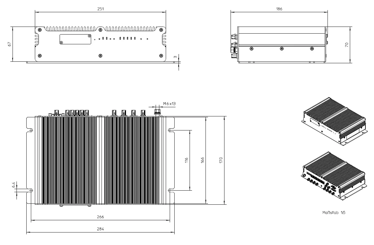
- Mounting: Use four M6 screws with washers to secure the device on a flat, stable surface.
- Earthing: Connect the M6 earthing stud on the front panel to protective earth using a cable with at least 2.5 mm² cross-section. Tighten the nut to 3 Nm.
- Electrical Connection: Ensure the power supply voltage is between 12 V and 24 VDC. The device starts automatically upon receiving power; there is no on/off switch.
SIM Card Installation
To install SIM cards:
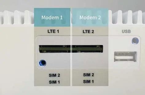
- Remove the service cover using a Torx 10 screwdriver.
- Insert the SIM cards into the appropriate slots.
- Replace the cover and tighten the screws to a maximum torque of 0.55 Nm.
Note: Switching between SIM slots takes approximately 30 seconds. Slot 1 is preselected at power-up.
Reset and Maintenance
The device includes a hidden reset switch accessible via a paper clip through a hole on the front panel:
- < 2 seconds: Reset after release.
- 2-5 seconds: No action.
- > 5 seconds: Remove custom configuration and reset.
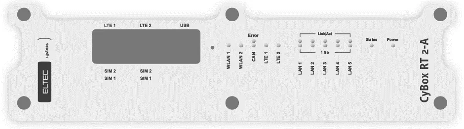
The front panel LEDs provide status updates for Power, Status, Modules (WLAN/LTE), and LAN activity. If the device becomes very hot (> 80°C), ensure it is protected from accidental contact and allowed to cool before maintenance.
Practical help
Common problems
Device overheating
Ensure at least 150 mm of free space around the housing and mount with connectors facing down.
SIM switching delay
Switching takes about 30 seconds. Use slot 1 for the primary SIM to avoid delays during booting.
Reset switch not responding
Ensure the device has fully booted (approx. 1 minute) before attempting to use the reset switch.
Before use
- Verify power supply voltage is between 12 V and 24 VDC.
- Ensure protective earth is connected to the M6 stud.
- Check that all cables are intact and undamaged.
- Ensure 150 mm clearance for heat dissipation.
- Verify that the device is mounted on a stable surface.
Specs in practice
- Input Voltage
- 12-24 VDC
- Protection Class
- IP40
- Earthing Torque
- 3 Nm
- SIM Cover Torque
- 0.55 Nm
Images and diagrams
- Front Panel: Shows SIM slots, USB port, and status LEDs.
- Back Panel: Shows all data, antenna, and power connectors.
- Earthing: Illustrates the M6 stud connection assembly.
Model compatibility
- LTE modules are intended for two antennas plus one GNSS antenna.
- WLAN modules are referred to as 'radio' in software.
- LTE modules are referred to as 'modem' in software.

Manual page author
Emily Carter
User documentation editor
Prepares concise manual descriptions and highlights the most useful setup, operation, and maintenance information for readers.