Home / Security
Extron Occupancy Sensor OCS 100C User Guide
Comprehensive setup and configuration guide for the Extron OCS 100C dual-technology occupancy sensor, covering installation, wiring, sensitivity adjustments, and troubleshooting.
Table of contents
Manual images
Jump to the sectionProduct Overview
The Extron OCS 100C is a dual-technology occupancy sensor designed to automate meeting and presentation spaces. It utilizes ultrasonic (US) and infrared (PIR) sensors, along with a photocell, to detect room occupancy and ambient light conditions. The sensor is compatible with Extron control products equipped with Digital I/O ports or via eBUS using optional interface accessories.
Safety and Installation
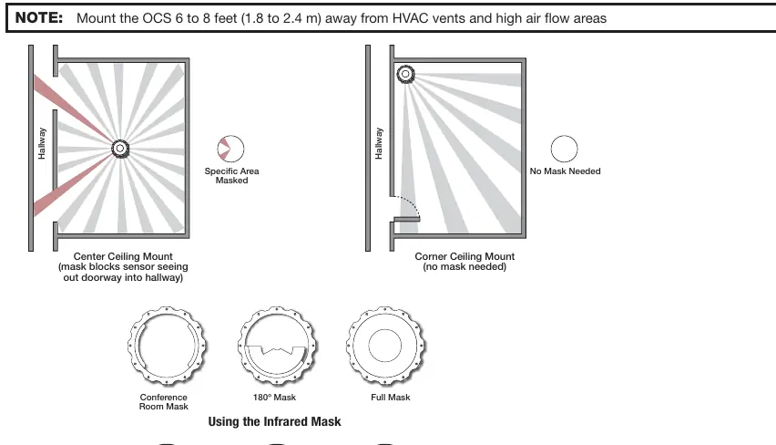
Installation must be performed by qualified personnel in accordance with local and national building and electrical codes. The device requires 24 VDC for operation. If local 24 V power is unavailable, the included PC 1224 power converter can be used to convert 12 VDC or USB 5 V power. The sensor should be mounted 6 to 8 feet away from HVAC vents and high airflow areas to prevent false detections. For optimal coverage, the sensor should be installed 10 feet above the coverage area.
Configuration and Setup
The OCS 100C features various DIP switches and adjustment dials to customize performance. By default, the sensor is set to require both PIR and US detection to trigger occupancy. Users can adjust sensitivity for infrared, ultrasonic, and photocell sensors manually or utilize the Automatic Mode, where the sensor learns ideal settings over time. A built-in timer allows for adjustable hold times ranging from 8 to 42 minutes. A test mode is available to verify sensor coverage and sensitivity settings during setup.
Operation and Maintenance
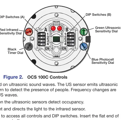
The sensor provides visual feedback via green (ultrasonic) and red (infrared) LED status indicators. If the sensor is too sensitive or not sensitive enough, adjustments can be made using the respective dials. Infrared masks are included to block specific areas, such as doorways, to prevent false triggers from hallway traffic. Regular maintenance involves ensuring the sensor remains clear of obstructions and verifying that sensitivity settings remain appropriate for the room environment.
Troubleshooting
If the sensor remains ON, it may be due to constant noise; try reducing sensitivity or removing the noise source. If the sensor remains OFF, increase sensitivity. If the sensor stays on too long, reduce the timer setting. If hallway traffic triggers the sensor, use the provided IR masks or reposition the sensor.
Manufacturer information
Extron Electronics
Practical help
Common problems
Sensor remains ON
Reduce sensitivity dials by 15% or remove the noise source.
Sensor remains OFF
Increase sensitivity dials by 15% or check DIP switch A2 settings.
Sensor remains on too long
Reduce the timer setting using the black dial.
Hallway traffic triggers sensor
Reposition the sensor or install the included IR masks.
Before use
- Ensure 24 VDC power source is available or use the PC 1224 converter.
- Mount the sensor 6-8 feet away from HVAC vents.
- Verify DIP switch settings (default is recommended for initial setup).
- Set the sensor to Test Mode to verify coverage.
- Confirm all wiring connections are secure and share a common ground.
- Install IR masks if blocking specific areas is required.
Specs in practice
- Photocell Range
- 10 to 1000 LUX; prevents triggering when natural light is sufficient.
- Power Requirement
- 24 VDC operation.
Images and diagrams
- Front Panel: Shows sensor locations, LED indicators, and adjustment dials.
- DIP Switches: Configure dual-technology mode, LED status, and automatic/manual adjustments.
- Wiring Diagrams: Illustrate connections for external power supplies and control processors.
- Mask Patterns: Demonstrate how to block specific areas to refine sensor coverage.
- Installation: Details the twist-lock mounting process for ceiling tiles.
Model compatibility
- Compatible with Extron control products with Digital I/O ports.
- Supports eBUS connectivity via optional interface accessories.
- Requires Class III SELV systems for power.

Manual page author
Michael Turner
Technical manual editor
Reviews PDF manuals for structure, safety notes, and practical product details so readers can find the right information quickly.